
Summary of Contents for Q-SYS SPA-Qf Series
- Page 1 Hardware User Manual Q-SYS SPA-Qf Series Network Amplifiers SPA-Qf 60x2 2-Channel Amplifier with FlexIO SPA-Qf 60x4 4-Channel Amplifier with FlexIO TD-001669-01-A *TD-001669-01*...
-
Page 2: Important Safety Instructions
EXPLANATION OF TERMS AND SYMBOLS The term “WARNING” indicates instructions regarding personal safety. Failure to follow them may result in bodily injury or death. The term “CAUTION” indicates instructions regarding possible damage to physical equipment. Failure to follow them may result in equipment damage to equipment that may not be covered under the warranty. -
Page 3: Maintenance And Repair
Reduced amplifier output can be expected when the ambient temperature exceeds 35°C. Amplifier will shut down when the hardware temperature exceeds 73°C. NOTE: Q-SYS SPA-Qf amplifiers are convection-cooled and therefore can become warm to the touch. This is normal and expected. - Page 4 RoHS Statements The QSC Q-SYS SPA-Qf models are in compliance with European RoHS Directive. The QSC Q-SYS SPA-Qf models are in compliance with “China RoHS” directives. The following table is provided for product use in China and its territories. QSC Q-SYS SPA-Qf Models 部件名称...
-
Page 5: What's In The Box
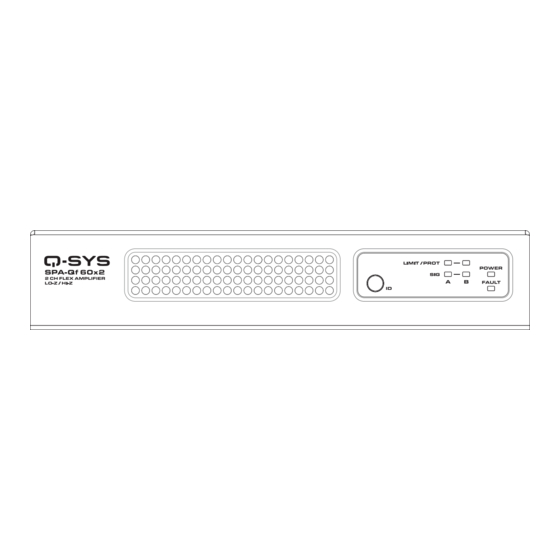
TD-001663 Introduction Q-SYS SPA-Qf Series network amplifiers continue the Q-SYS trend of empowered peripherals with a solution that not only delivers low- power amplification to smaller spaces such as meeting and conference rooms, but also supports flexible Q-SYS system configuration and control. - Page 6 5. Fault LED – The amplifier is unable to pass audio or is malfunctioning or not properly configured (fast flashing orange). This could be caused by broken audio streams, amplifier fault, or loudspeaker short circuit. Refer to the Status component in Q-SYS Designer Software for fault details.
- Page 7 5. Fault LED – The amplifier is unable to pass audio or is malfunctioning or not properly configured (fast flashing orange). This could be caused by broken audio streams, amplifier fault, or loudspeaker short circuit. Refer to the Status component in Q-SYS Designer Software for fault details.
-
Page 8: Rack Installation
Ventilation Requirements There must be at least 6 inches of open space measured from back of amplifier. NOTE: To maintain safe operating temperatures, Q-SYS SPA-Qf Series amplifiers contain advanced protection circuitry that reduces output power to lower the operating temperature when needed. - Page 9 Two Amplifiers in 19-inch Rack Install two SPA-Qf amplifiers side-by-side using two (2) foam spacers, two (2) rack ears, six (6) Phillips pan head screws, one (1) joining plate, and six (6) Phillips flat head screws. Flat Head Screws Bottom Side Front Panel Foam Spacers Pan Head Screws...
- Page 10 Optional – Adjusting Front Panel Alignment To achieve proper front panel alignment with other rack equipment, use the two (2) supplied rack ear spacers. (Rack and rack-mounting screws and washers are pictured but not supplied.) Spacer Spacer Spacer Surface Mount Under a Table, on a Wall, or Behind a Display When surface-mounting an SPA-Qf amplifier, use two (2) joining plates, six (6) flat head screws, and four (4) screws for attaching the unit to the surface (not supplied).
-
Page 11: Output Connectors
Connections Wire Strip length = 5mm. DO NOT TIN! IMPORTANT: Class 2 Wiring. Output Connectors SPA-Qf 2-Channel SPA-Qf 4-Channel Flex Connectors Balanced Unbalanced CAUTION! A single channel consists of three pins. It is possible to plug in a connector that straddles two channels. -
Page 12: Output Modes
Stereo Mode CAUTION! Do not connect any output to ground. 4 or 8-ohm Bridged Mode Configure the bridge mode in Q-SYS Designer Software. CAUTION! Do not connect any output to ground. 70V / 100V Bridged Mode Configure the bridge mode in Q-SYS Designer Software. - Page 13 The following diagram shows where gain, muting, and limiting are applied within the input to output signal flow, as well as the QDS components used to configure parameters. The analog inputs are converted to digital audio in the amplifier. The converted audio is then routed to the Q-SYS Core via Q-LAN (LAN A).
-
Page 14: Amplifier Sensitivity
Gain There are multiple places within Q-SYS to add gain to your system. Within the amplifier, it is critical to understand that the gain within the Speaker component should typically not be above +10dB. This is due to the dynamic nature of music and the stress that this can put... -
Page 15: Warranty
© 2023 QSC, LLC All rights reserved. QSC, the QSC logo, Q-SYS, and the Q-SYS logo are registered trademarks of QSC, LLC in the U.S. Patent and Trademark Office and other countries. Patents may apply or be pending. All other trademarks are the property of their respective owners.
Need help?
Do you have a question about the SPA-Qf Series and is the answer not in the manual?
Questions and answers