
Summary of Contents for Kessler-Ellis Products SUPERtrol-I MS-716
- Page 1 SUPERtrol-I MS-716 omputer KESSLER-ELLIS PRODUCTS 10 Industrial Way East Eatontown, NJ 07724 800-631-2165 • 732-649-7100 Fax: 732-649-7099 99793 10/21/21...
- Page 2 WARNING! Power, input and output (I/O) wiring must be in accordance with Class I, Division 2 wiring methods Article 501-4 (b) or the National Electrical Code, NFPA 70 for installations in the U.S., or as specified in Section 18-1J2 of the Canadian Electrical Code for installations within Canada and in accordance with the authority having juristiction.
-
Page 3: Table Of Contents
SUPERtrol-I MS-716 Flow Computer CONTENTS 1. DESCRIPTION 1.1 Unit Description ......................1 1.2 Unit Features ........................ 1 1.3 Specifications ....................... 2 2. INSTALLATION 2.1 General Mounting Hints ....................6 2.2 Mounting Diagrams ...................... 6 3. APPLICATIONS 3.1 Liquid Volume ....................... 7 3.2 Corrected Liquid Volume .................... - Page 4 SUPERtrol-I MS-716 Flow Computer CONTENTS 8. TEST, SERVICE and MAINTENANCE 8.1 Test Menus ......................... 45 8.2 Test Sub-Menus ......................46 8.2.1 Audit Trail ....................46 8.2.2 Error History ....................46 8.2.3 Print System Setup ..................46 8.2.4 Keypad test ....................47 8.2.5 Display test ....................
-
Page 5: Description
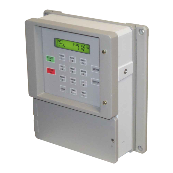
Unit Description 1. Description 1.1 Unit Description: The SUPERtrol-I MS-716 Flow Computer is a special version of the SUPERtrol-1 Flow Computer which is supplied in a vehicle mount enclosure. The SUPERtrol-I MS-716 satisfies the instrument requirements for a variety of flowmeter types in liquid applications. Multiple flow equations and instrument functions are available in a single unit with many advanced features. -
Page 6: Specifications
SUPERtrol-I MS-716 Flow Computer 1.3 Specifications: Specifications: Pulse Inputs: Number of Flow Inputs: one Environmental Altitude up to 2000m Configurations supported: single input with or Operating Temperature: 0°C to +50°C without quadrature (menu selectable) (-20°C to 55°C optional) Input Impedance: 10 KΩ nominal Storage Temperature: -40°C to +85 C M a x i m u m... - Page 7 SUPERtrol-I MS-716 Flow Computer Relay Outputs Operating Mode The relay outputs are menu assignable to The Flow Computer can be thought of as making a (Individually for each relay) Low Rate Alarm, Hi Rate series of measurements of flow, temperature/density...
- Page 8 SUPERtrol-I MS-716 Flow Computer Setup Mode Maintenance Mode: The setup mode is password protected by means The Maintenance Mode of the Flow Computer is the of a numeric lock out code established by the user. Test and Calibration Mode for the device. This mode...
- Page 9 SUPERtrol-I MS-716 Flow Computer Operation of Serial Port with Modems (optional) Operation of Serial Communication Port with The Flow Computer RS-232 channel supports a Printers Flow Computer’s RS-232 channel supports a number of operating modes. One of these modes number of operating modes. One of these modes...
-
Page 10: Installation
SUPERtrol-I MS-716 Flow Computer 2. Installation 2.1 General Mounting Hints: General Mounting Hints Termination Connectors: Minimum Wire Gauge: 22 AWG Maximum Wire Gauge: 14 AWG Voltage/current limits are limited by unit specifications. Permanently Connected Equipment: UL 3101-1, Section 6.12.2.1 specifies that: •... -
Page 11: Applications
SUPERtrol-I MS-716 Flow Computer 3. Applications 3.1 Liquid Volume Liquid Volume Measurements: A flowmeter measures the actual volume in a liquid line. A temperature sensor can also be installed to correct for liquid thermal expansion (see 3.2 Corrected Volume). Calculations: •... -
Page 12: Corrected Liquid Volume
SUPERtrol-I MS-716 Flow Computer Corrected 3.2 Corrected Liquid Volume Liquid Volume Measurements: A flowmeter measures the actual volume in a liquid line. A temperature sensor is installed to correct for liquid thermal expansion. Calculations: • Corrected Volume is calculated using the flow and temperature inputs as well as the thermal expansion coefficient stored in the flow computer. -
Page 13: Liquid Mass
SUPERtrol-I MS-716 Flow Computer Liquid Mass 3.3 Liquid Mass Measurements: Actual volume is measured by the flow element (DP transmitter, Flowmeter). Temperature is measured by the temperature transmitter. A density transmitter can be used for direct density measurements. Calculations: • The density and mass flow are calculated using the reference density and the thermal expansion coefficient of the liquid (see "SET FLUID... -
Page 14: Batching
SUPERtrol-I MS-716 Flow Computer Batching 3.4 Batching Measurements: A flowmeter measures the actual volume in a liquid line. A temperature sensor can also be installed to correct for liquid thermal expansion (see 3.2 Corrected Volume). Calculations: • For Flowmeters with Pulse Outputs, Volume flow is calculated using the flowmeter frequency output and the user entered K-Factor. -
Page 15: Wiring
SUPERtrol-I MS-716 Flow Computer 4 WIRING 4.1 Typical Batcher Wiring: Batcher Wiring Optional Wiring for DC OUTPUT Signal Flow Sensor with Preamp FLOW PULSE IN 1 Vin + (+) V PULSE IN 2 Iin + Common Signal COMMON --------- Vin + Com. -
Page 16: Wiring In Hazardous Areas
SUPERtrol-I MS-716 Flow Computer 4.3 Wiring In Hazardous Areas: Examples using MLT787S+ Barrier (MTL4755ac for RTD) Flow Input Flow Input Hazardous Area Safe Area 4-20 4-20mA Flow 24V Out Diode Transmitter Q/∆P – 4-20mA In Common Temperature Input Temperature Input (4-20mA Transmitter) -
Page 17: Unit Operation
SUPERtrol-I MS-716 Flow Computer 5. UNIT OPERATION 5.1 Front Panel Operation Concept for Run Mode The Flow Computer is fully programmable through the front panel. Please review the following us- age summary before attempting to use the instrument. TOTAL RATE... -
Page 18: General Operation
SUPERtrol-I MS-716 Flow Computer General 5.2 General Operation Operation The unit can display: Rate, Total, Grand Total, Temperature, Density, Presets and Time of Day. The Temperature and/or Density can be displayed even if you are using the Volumetric Flow Equation (a Temperature or Density sensor must be installed). -
Page 19: Rs-232 Serial Port Operation In Rate/Total Mode
SUPERtrol-I MS-716 Flow Computer RS-232 Serial Port 5.3.5 RS-232 Serial Port Operation in Rate/Total mode (Rate/Total mode) The RS-232 serial port can be used for programming (using the Setup Disk) or for communicating to printers and computers in the Operating Mode (Run Mode). -
Page 20: Batcher Operation
SUPERtrol-I MS-716 Flow Computer 5.4 Batcher Operation The Batcher mode is used primarily to control batches. The main difference between the Batch mode and Rate/Total mode is the relay operation. The Batch mode allows the operator to "START" the unit via the front panel or remote input. Once started, the relays (RLY1 &... -
Page 21: Password Protection For Batcher Mode
SUPERtrol-I MS-716 Flow Computer Slow Start Quantity The Slow Start Quantity is a function that allows an amount to be entered for a Slow Start up. This function requires two stage valve control. RLY 1 (slow flow) will energize for Slow Start and RLY 2 (fast flow) will energize after the Slow Start Quantity has been delivered. -
Page 22: Rs-232 Serial Port Operation In Batcher Mode
SUPERtrol-I MS-716 Flow Computer 5.4.6 RS-232 Serial Port Operation in Batcher mode RS-232 Serial Port (Batch mode) The RS-232 serial port can be used for programming (using the Setup Disk) or for communicating to printers and computers in the Operating Mode (Run Mode). -
Page 23: Programming
SUPERtrol-I MS-716 Flow Computer 6. PROGRAMMING 6.1 Front Panel Operation Concept for Program Mode The Flow Computer is fully programmable through the front panel. Please review the following usage summary before attempting to use the instru- ment. TOTAL RATE PRE 1... -
Page 24: Ez Setup
SUPERtrol-I MS-716 Flow Computer 6.2 EZ Setup The EZ Setup routine is a quick and easy way to configure the unit for the most commonly used instrument functions. This setup assumes that you are measuring Volumetric Flow using a high level, DC Pulsing flow sensor. -
Page 25: Setup Sub-Menus
SUPERtrol-I MS-716 Flow Computer 6.3 Setup Menus Menus Display Notes 6.3.1 Select Setup to enter the instrument setup SELECT OPERATE STATE Top Level Setup routine. Setup Test Menu MENU ENTER Refer to Page 20 for Details. STOP SELECT EZ SETUP START 6.3.2... - Page 26 SUPERtrol-I MS-716 Flow Computer 6.4 Setup Sub-Menus Sub-menus Display Notes Refer to page 20 for EZ Setup routine. 6.4.1 SELECT EZ SETUP SELECT EZ SETUP Press the DOWN (stop) key to advance to STOP Instrument Type. Press the UP (start) key to START advance to Administrative Setup.
- Page 27 SUPERtrol-I MS-716 Flow Computer Sub-menus Notes Press ENTER to enter Instrument Type sub- 6.4.2 INSTRUMENT TYPE menus. INSTRUMENT TYPE (continued) Enter the Slow Fill Rate. SLOW FILL RATE Press ENTER to store. ENTER Enter the Full Fill Rate (Fast Fill Rate). Press FULL FILL RATE ENTER to store.
-
Page 28: Setup Indicators (Density)
SUPERtrol-I MS-716 Flow Computer Sub-menus Notes Display Press ENTER to enter Select Flow Equation 6.4.3 SELECT FLOW EQUATION SELECT submenus. FLOW EQUATION ENTER Press ENTER when desired flow equation is SELECT FLOW EQUATION flashing. Volume Mass Cor/Vol ENTER Advance To... -
Page 29: Setup Indicators (Temperature)
SUPERtrol-I MS-716 Flow Computer Sub-menus Display Notes Press ENTER when Rate is flashing to 6.4.6 SETUP INDICATORS SETUP configure the Ratemeter Indicators Total Dens Rate Temp INDICATORS (Rate) ENTER Select the desired Rate Time Base. RATE TIME BASE Hour ENTER... -
Page 30: Setup Flow Input (Pulse - Ain & Ps (A=B))
SUPERtrol-I MS-716 Flow Computer Sub-menus Display Notes Press ENTER to begin setup of Flow Input. 6.4.8 SETUP FLOW INPUT SETUP FLOW INPUT (Pulse - Ain & PS ENTER (A=B)) Select the desired Excitation Voltage. EXCITATION VOLTAGE ENTER Press ENTER when Pulse is flashing to FLOW INPUT TYPE configure the flow input for Pulse signals. - Page 31 SUPERtrol-I MS-716 Flow Computer Submenus Display Notes Press ENTER to begin setup of Flow Input. 6.4.9 SETUP FLOW INPUT SETUP FLOW INPUT (Pulse - Quadrature, ENTER Qx1 or Qx2) Select the desired Excitation Voltage. EXCITATION VOLTAGE ENTER Press ENTER when Pulse is flashing to FLOW INPUT TYPE configure the flow input for Pulse signals.
-
Page 32: Setup Aux Input
SUPERtrol-I MS-716 Flow Computer Sub-menus Display Notes Press ENTER to begin setup of the Flow 6.4.10 SETUP FLOW INPUTS SETUP Input. FLOW INPUT (Analog) ENTER Select the desired Excitation Voltage. EXCITATION VOLTAGE ENTER Press ENTER when Analog is flashing to FLOW INPUT TYPE configure the flow input for Analog signals . -
Page 33: Set Fluid Properties
SUPERtrol-I MS-716 Flow Computer Sub-menus Display Notes Press ENTER to begin setup of the Auxiliary 6.4.11 SETUP AUX INPUT SETUP AUX INPUT Input. ENTER Select Temperature to set the Auxiliary Input NOTE: AUX INPUT TYPE When Density (Dens) for Temperature inputs. -
Page 34: Setup Pulse Output
SUPERtrol-I MS-716 Flow Computer Sub-menus Display Notes Press ENTER at this prompt to Set Fluid 6.4.12 SET FLUID PROPERTIES SET FLUID Properties. PROPERTIES ENTER Enter the Reference Density. This is used in the calculation of density when you have a REF. -
Page 35: Setup Relays
SUPERtrol-I MS-716 Flow Computer Sub-menus Display Notes 6.4.14 Press ENTER when Analog is flashing to SETUP ANALOG OUTPUT SETUP setup the Analog Output. ANALOG OUTPUT ENTER Select the desired Analog Output Usage. ANALOG OUTPUT USAGE Rate Total Temp Dens ENTER Only if Rate selected &... -
Page 36: Setup Control Inputs(Rate/Total)
SUPERtrol-I MS-716 Flow Computer Sub-menus Display Notes 6.4.15 (Continued) Select the desired Relay for setup. SETUP RELAYS SETUP RELAYS (Relays 3 & 4 Optional) Rly3 Rly4 Rly1 Rly2 (Relay 3 & Relay 4) ENTER NOTE: If Relay 3 Selected, Choose Rate, Total, Aux,... -
Page 37: Setup Control Inputs(Batch)
SUPERtrol-I MS-716 Flow Computer Sub-menus Display Notes Press Enter to begin setup of the Control 6.4.16 SETUP CONTROL INPUTS SETUP CONTROL Inputs. INPUTS (RATE/TOTAL) ENTER Select the desired Control Input for setup. SETUP CONTROL INPUTS Input1 Input2 Input3 ENTER If Control Input 1 Selected, CONTROL INPUT1 USAGE Select Inhibit Total or NA (Not Assigned). -
Page 38: Setup Realtime Clock(Time)
SUPERtrol-I MS-716 Flow Computer Sub-menus Display Notes 6.4.18 Press Enter to begin setup of the Realtime SETUP REALTIME CLOCK SETUP REALTIME Clock. CLOCK (Time) ENTER Select Time to set the time. SETUP REALTIME CLOCK Time Date ENTER Select 24Hr or 12Hr clock... - Page 39 SUPERtrol-I MS-716 Flow Computer Sub-menus Display Notes 6.4.20 Press Enter to begin setup of the Serial Port. SERIAL USAGE SERIAL USAGE ENTER Select Serial Hardware type for standard port. SERIAL HARDWARE (See SETUP NETWORK CARD for RS485 RS232 RS485 Modbus option) ENTER Select the Device ID.
- Page 40 SUPERtrol-I MS-716 Flow Computer Sub-menus Display Notes 6.4.20 Enter the Call Out Phone Number to be dialed CALL OUT PHONE # SERIAL USAGE for "Call Out Time" or "Print On Error/Alarm". (continued) ENTER Enter the number of redials to be performed NUMBER OF REDIALS on call out time if busy or no answer.
-
Page 41: Set Datalog/Print(Configure)
SUPERtrol-I MS-716 Flow Computer Sub-menus Display Notes 6.4.22 Press enter to begin Setup Datalog/Print SET DATALOG/PRINT SETUP routine. DATALOG/PRINT (Select_list) ENTER Press enter when Select_list is selected to SET DATALOG/PRINT setup print list. Select_list Config Use Up and Down arrow keys to view list PRINT LIST ITEMS status. - Page 42 SUPERtrol-I MS-716 Flow Computer Press Enter to setup Network Card 6.4.24 SETUP NETWORK CARD SETUP NETWORK CARD (optional) ENTER Select desired Network Protocol. SELECT NTW PROTOCOL ModbusRTU ENTER Enter the device address on network (00- NETWORK DEVICE ID 255). ENTER Select the desired Baud Rate.
-
Page 43: Principle Of Operation
SUPERtrol-I MS-716 Flow Computer 7. Principle Of Operation General 7.1 General: Operation The Flow Computer uses several internal calculations to compute the compensated flow based on specific data input. Several computations are performed to arrive at the uncompensated flow, temperature, density and viscosity. This information is then used to compute the Corrected Volume Flow or Mass Flow. - Page 44 SUPERtrol-I MS-716 Flow Computer 7.3 Flow Equations: (Continued) Flow Equations Input Viscosity Computation: A exp (Deg F + 459.67) † centistokes = Absolute Density Where: centistokes = cP/(kg/l) Uncompensated Flow Computation: Pulse Input; Average K-Factor input frequency * time scale factor...
- Page 45 SUPERtrol-I MS-716 Flow Computer 7.3 Flow Equations: (Continued) Flow Equations The above information was obtained from "Flow Measurement Engineering Handbook, 3rd Edition" by Richard W Miller.
-
Page 46: Calculating The Expansion Factor
SUPERtrol-I MS-716 Flow Computer 7.4 Calculating the Expansion Factor Calculating The liquid density is a function of the flowing temperature for many fluids. This unit solves an equation which represents this physical property of the fluid. Expansion Factor The information which the unit uses to describe the fluid is entered by the user in the following variables: Reference Temperature, Reference Density, Expansion Factor. -
Page 47: Computation Of Viscosity Coef. A And B
SUPERtrol-I MS-716 Flow Computer 7.5 Computation of Viscosity Coef. A and B The flow computer solves an equation which computes the viscosity Computation of as a function of temperature. Two parameters must be entered for this Viscosity calculation to be performed. These are the setup parameters Viscosity Coef. -
Page 48: Linearization Table
SUPERtrol-I MS-716 Flow Computer 7.6 Linearization Table Linearization 7.6.1 Linearization Table General Information The Linearization Table is used when the flow input device gives a nonlinear Table input signal. The unit uses up to 16 different points, as entered by the General operator, to form a curve for linearizing the input signal. -
Page 49: Test, Service And Maintenance
SUPERtrol-I MS-716 Flow Computer 8. Test, Service and Maintenance 8.1 Test Menus Menus Display Notes Select Test to enter the instrument 8.1.1 test & calibration routine. SELECT OPERATE STATE TOP LEVEL Test NOTE: Supervisor (Service) password Setup TEST MENUS required to gain access to this mode. - Page 50 SUPERtrol-I MS-716 Flow Computer 8.2 Test Sub-Menus Sub-menus Display Notes 8.2.1 Press Enter to view the audit trail information. Audit Trail Audit Trail Submenu Group ENTER The audit trail is viewed in this format: nnnnn= number of critical menu changes,...
-
Page 51: Keypad Test
SUPERtrol-I MS-716 Flow Computer Sub-menus Display Notes Press Enter to enter keypad test 8.2.4 Keypad test Keypad test Submenu Group ENTER Press the various keys and the display will show the key that was pressed. Press Menu Keypad test to exit the test Key pressed—>... -
Page 52: Calibrate Ch1 0Ma
SUPERtrol-I MS-716 Flow Computer ALL UNITS ARE CALIBRATED AT THE FACTORY PRIOR TO SHIPMENT CAUTION: This unit must be calibrated using precision and calibrated equipment. Equipment needed is as follows: Frequency Generator, Digital Multimeter, Precision Current/Voltage Source, Oscilloscope, Frequency Counter. -
Page 53: Calibrate Ch2 20Ma
SUPERtrol-I MS-716 Flow Computer Sub-menus Display Notes To Calibrate: Connect Current Source (+) 8.2.8 Calibrate ch2 Calibrate CH2 0mA TB1-8, (-) TB1-4. Input 0mA and press Enter. Iin=TB1-8 GND=TB1-4 Submenu Group ENTER This message is displayed during calibration. Calibrate ch2 0 CALIBRATING ——... -
Page 54: Calibrate Ch1 10V
SUPERtrol-I MS-716 Flow Computer Sub-menus Display Notes To Calibrate: Connect Voltage Source (+) 8.2.10 Calibrate ch1 Calibrate CH1 0V TB1-2, (-) TB1-4. Input 0V and press Enter. Vin=TB1-2 GND=TB1-4 Submenu Group ENTER This message is displayed during calibration. Calibrate ch1 0 CALIBRATING ——... -
Page 55: Calibrate Ch2 10V
SUPERtrol-I MS-716 Flow Computer Sub-menus Display Notes To Calibrate: Connect Voltage Source (+) 8.2.12 Calibrate ch2 Calibrate CH2 0V TB1-5, (-) TB1-4. Input 0V and press Enter. Vin=TB1-5 GND=TB1-4 Submenu Group ENTER This message is displayed during calibration. Calibrate ch2 0 CALIBRATING ——... -
Page 56: Calibrate 20Ma Out
SUPERtrol-I MS-716 Flow Computer Sub-menus Display Notes Connect ammeter to (+) TB1-15, (-) TB1-16. 8.2.15 Calibrate 0mA out Calibrate 4mA Out Press enter. + TB1-15 - TB1-16 Submenu Group ENTER To trim 0mA output: Press CLEAR to enable editing and enter a small negative number (i.e. -
Page 57: Pulse Input Test
SUPERtrol-I MS-716 Flow Computer Sub-menus Display Notes top-level menu. 8.2.18 Pulse input test Pulse input test Submenu Group Press Enter key to test the pulse input. ENTER 2.5V Use the Up/Down arrow keys to select the Pulse input test STOP... -
Page 58: Pulse Out Test
SUPERtrol-I MS-716 Flow Computer Sub-menus Display Notes Press Enter key to test the pulse output. 8.2.21 Pulse out test Pulse out test Submenu Group To simulate a frequency on the pulse output: ENTER Connect a frequency counter to (+)TB1-13, (-)TB1-14. Press the key under the desired Pulse out test setting to move the asterisk (*). -
Page 59: Battery Voltage Test
SUPERtrol-I MS-716 Flow Computer Sub-menus Display Notes Press Enter key to view the battery voltage. 8.2.24 Battery Voltage Test Battery Voltage test Submenu Group ENTER The display will show the battery voltage. Battery Voltage Test Replace battery at 2.5 VDC or below. -
Page 60: Internal Fuse Replacement
SUPERtrol-I MS-716 Flow Computer 8.3 Internal Fuse Replacement Instructions: 1. Make sure you follow proper E.S.D. Precautions. All persons performing this replacement must follow proper grounding procedures. 2. Turn the power to the unit off. 3. Remove the seal on the lower panel cover and remove screw from the lower panel cover (see fig. -
Page 61: Instrument Setup By Pc Over Serial Port
SUPERtrol-I MS-716 Flow Computer 9. RS-232 Serial Port 9.1 RS-232 Port Description: The Flow Computer has a general purpose RS-232 Port which may be used for any one of the following purposes: Transaction Printing Data Logging Remote Metering by Modem (optional) -
Page 62: Rs-485 Serial Port
SUPERtrol-I MS-716 Flow Computer 10. RS-485 Serial Port (optional) 10.1 RS-485 Port Description: The Flow Computer has a an optional general purpose RS-485 Port which may be used for any one of the following purposes: Accessing Process Parameters Rate, Temperatures, Density, Setpoints, Month, Day, Year, Hour, Min- utes, Seconds, etc. -
Page 63: Flow Computer Setup Software
SUPERtrol-I MS-716 Flow Computer 11. Flow Computer Setup Software The Flow Computer setup program provides for configuring, monitoring and controlling a Flow Computer unit. Sample applications are stored in disk files. The setup program calls these Templates. You can store the setup from the program’s memory to either the Flow Computer (Downloading the file) or to a disk file (Saving the file) for later usage. -
Page 64: Using The Flow Computer Setup Software
SUPERtrol-I MS-716 Flow Computer 11.4 Using the Flow Computer Setup Software The setup software window consists of several menu “Tabs”. Each tab is organized into groups containing various configuration and/or monitoring functions. To view the tab windows, simply click on the tab. The previous tab window will be hidden as the new tab window is brought to the foreground. -
Page 65: View Tab
SUPERtrol-I MS-716 Flow Computer 11.7 View Tab The View Tab screen allows for viewing selected group items on the PC in a similar format as shown on the unit display. Data from the following groups can be viewed in the List of Values section: Process Parameters (i.e. -
Page 66: Glossary Of Terms
SUPERtrol-I MS-716 Flow Computer 12. Glossary Of Terms Acknowledge & Clear Alarms Acknowledge is used to clear alarm relays and remove any visual alarm messages from the display. In the run mode, press the ENTER key or activate CONTROL INPUT 3 (if set for ACK) to momentarily clear alarms and alarm messages. Alarms will reassert themselves if alarm conditions are still present. Analog Output The analog signal (4-20mA) that is generated by the Flow Computer. It can correspond to the Rate, Total, Temperature or Density. This output is used primarily for transmission of process information to remote systems. Audit Trail The audit trail is used to track the number of changes made to the units setup program. Batch Count Mode Batch Count Mode specifies the user preference for count direction. The "Up" selection begins with a value of "0" and counts up until the batch size is reached. The "Down" selection begins with a value equal to the desired batch size and counts down to "0". Batch Overrun The Flow Computer offers a batch overrun compensation routine. If batch overrun occurs due to slow valve response time, the unit will compensate for the overrun amount on the next batch. This feature can be disabled if desired. Batcher An instrument which controls the dispensing of desired batch amounts. Liquid batching systems are usually comprised of a batch controller (batcher), flowmeter and control valve. The batcher opens and closes the valve... - Page 67 SUPERtrol-I MS-716 Flow Computer 12. Glossary Of Terms (Continued) Flow Signal Timeout The Flow Signal Timeout allows the user to enter a timeout of 0 to 99 seconds. If a batch is “Filling” and zero flow persists for more than the user entered time then the batch will be aborted. This prevents over flows due to faulty flow sensors and/or wiring. Flow Equation A flow control expression or algorithm describing a mathematical equation to be solved by a flow computer in the desired application. Follow, Alarm Alarm relays which are non latching and whose output state is based solely on the comparison of the current process value and the alarm setpoint (trip point). Function Key A key on a push-button panel or keyboard (whose function is described by the key label) used to perform an instrument function or special routine. Handshake A means of controlling the information flow between two pieces of equipment to prevent the sending device from transmitting information at a rate faster than what can be accepted by the receiver. Hysteresis The relay hysteresis is a "dead band" setting which allows the relay to remain energized for a given amount below the setpoint. This is used to prevent relay chatter when the process value is near the setpoint value. Example: If the Preset is set at 100, and the hysteresis is set at 10, the relay will energize when the rate, temp or dens. reaches 100, the relay will remain energized until the reading falls below 90. Input Termination Input signal lines on digital inputs often require pullup or pulldown resistor configurations to operate properly with different sensor configurations. The Flow Computer contains such resistors and may be enabled via the setup menu.
- Page 68 SUPERtrol-I MS-716 Flow Computer 12. Glossary Of Terms (Continued) Maximum Batch Preset The Maximum Batch Preset allows the user to program the Maximum Batch value allowed to be entered by the operator. If an operator should try to program a batch higher then this value, the unit will not allow the value to be entered and will prompt the user with an error message saying that the Maximum Batch Preset has been exceeded. Maximum Drain Time The unit declares that a batch is “done” when the flow rate equals “0”. A flow rate may be present long after the Preset Relay de-energizes due to slow reacting valves or leaky valves. The Maximum Drain Time allows the user to enter an amount of time (0 to 99 seconds) to wait before declaring “Batch Done”. After the Preset Batch quantity is reached, the unit will declare “Batch Done” when the flow rate is “0” or the Maximum Drain Time has expired. The batch data will then be available for printing and datalogging. Max Window The max. window time sets the maximum sample time (1 to 99 sec) for the ratemeter. Modem Init Master The "Modem Init Master" menu allows the user to select whether the unit will engage in a configuration conversation with the modem on power up or impart no setup information to the modem and use it "as is". For most users it is recommended to choose "yes" for "Modem Init Master". Orifice Plate Flowmeter A class of flow measurement devices where the measured signal (differential pressure) has a square law relationship to flow. Parity A method for detecting errors in transmissions of serial communications data. Preset A set point used to trigger the relay outputs of the Flow Computer.
- Page 69 SUPERtrol-I MS-716 Flow Computer 12. Glossary Of Terms (Continued) Rate Averaging Filter The rate averaging filter is used to stabilize fluctuating rate displays. Higher settings provide more averaging for a more stable display. Derived from the equation: (OLD DATA x "Avg. Filter" + NEW DATA) ("Avg. Filter" + 1) Ratemeter Any device used to display the speed of a process. The ratemeter in the Flow Computer displays flow rate. Ref. Dens. Abbreviation for Reference Density. This is the fluid density at reference temperature. Ref. Temp. Abbreviation for Reference Temperature. This represents the base or reference condition to which corrected flow will be computed. Reset/Start Control Input In a batching system, a single operator activation of the START key or Control Input 1 will reset the total then start the batch process.
-
Page 70: Diagnosis And Troubleshooting
SUPERtrol-I MS-716 Flow Computer 13. Diagnosis and Troubleshooting 13.1 Response of Flow Computer on Error or Alarm: Error and warning indications which occur during operation are indicated in the RUN mode alternately with the measured values. The Flow Computer has three types of error:... -
Page 71: Diagnosis Flow Chart And Troubleshooting
SUPERtrol-I MS-716 Flow Computer 13.2 Diagnosis Flow Chart and Troubleshooting All instruments undergo various stages of quality control during produc- tion. The last of these stages is a complete calibration carried out on state-of-the-art calibration rigs. A summary of possible causes is given below to help you identify faults. -
Page 72: Error & Warning Messages
SUPERtrol-I MS-716 Flow Computer 13.3 Error & Warning Messages: 13.3.1 Error/Warning Message Cause Remedy Sensor/Process Alarms Displayed when totalizer Acknowledge TOTALIZER ROLLOVER rolls over Rollover, Remedy not required 4-20 mA Input current at aux • Check wiring AUX INPUT TOO LOW input smaller than 3.5 mA:... -
Page 73: Self Test Alarms
SUPERtrol-I MS-716 Flow Computer 13.3 Error & Warning Messages: (Continued) 13.3.2 Error/Warning Message Cause Remedy Self Test Alarms Analog input signal of the • Check analog FLOW INPUT TOO HIGH flow input exceeded by more signal range than 3%: • Check the •... -
Page 74: Appendix A - Setup Menus
SUPERtrol-I MS-716 Flow Computer APPENDIX A - Setup Menus... -
Page 75: Appendix B - Batching Diagrams
SUPERtrol-I MS-716 Flow Computer APPENDIX B - Batching Diagrams Typical Batcher Application with STANDARD Valve(s) Slow Fill Solenoid Valve Pulse Output Main Flowmeter Solenoid Valve with DC pulse output RS-232or RS-485 to Computer TOTAL RATE PRE 1 START MENU PRINT... - Page 76 SUPERtrol-I MS-716 Flow Computer Typical Batcher Application with DIGITAL CONTROL VALVE Pulse Output Digital Control Valve Flowmeter with DC pulse output RS-232or RS-485 to Computer TOTAL RATE PRE 1 START MENU PRINT GRAND TOTAL RATE PRE 1 PRINT STOP CLEAR...
Need help?
Do you have a question about the SUPERtrol-I MS-716 and is the answer not in the manual?
Questions and answers