Table of Contents
Advertisement
Advertisement
Table of Contents

Related Manuals for Dettson OTP-C Series


Summary of Contents for Dettson OTP-C Series
- Page 1 Owner’s Manual DUCTLESS SINGLE ZONE HEAT PUMP 23-20 SEER INVERTER 9 000 to 24 000 BTU/hr Models: OCD09KCH23S OCD12KCH22S OCD15KCH22S OCD18KCH20S OCD24KCH20S Please read this owner’s manual carefully before operating the unit and keep it for future reference. INS515-201601-07...
-
Page 2: Table Of Contents
TABLE OF CONTENTS Operation notices .................................3 Explanation of symbols ................................3 Precautions....................................4 Working temperature range ...............................6 Parts name ....................................7 Indoor unit screen display ..............................8 Remote control ..................................9 Buttons on remote control ..............................9 Icon identification on remote control display ......................9 Operation of remote control ............................ -
Page 3: Operation Notices
OPERATION NOTICES EXPLANATION OF SYMBOLS Indicates a hazardous situation that, if not avoided, DANGER will result in serious injury or death. Indicates a hazardous situation that, if not avoided, WARNING could result in serious injury or death. Indicates a hazardous situation that, if not avoided, CAUTION may result in minor or moderate injury. -
Page 4: Precautions
PRECAUTIONS WARNING Operation and Maintenance • This appliance can be used by people (including children of 8 years old and above) with reduced physical, sensory or mental capabilities, or lack of experience and knowledge, as long as they are under the supervision or instruction concerning use of the appliance by a person responsible for their safety. - Page 5 PRECAUTIONS WARNING Wiring • Installation must be performed by a qualified person. Otherwise, it may cause personal injury or damage. • Must follow the electric safety regulations when installing the unit. • According to the local safety regulations, use qualified power supply circuit and circuit breaker. •...
-
Page 6: Working Temperature Range
PRECAUTIONS WARNING Location • If you need to relocate the appliance to another place, only a qualified person can perform the work. Otherwise, it may cause personal injury or damage. • Select a location which is out of reach for children and far away from animals or plants. If it is unavoidable, please add a fence around the outdoor unit for safety purpose. -
Page 7: Parts Name
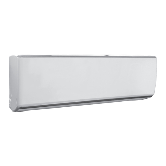
PARTS NAME Actual product may be different from below graphics, please refer to actual product NOTICE for reference purposes. Indoor unit Air inlet Panel Filter AUX button Horizontal louvre Air outlet Remote Control Outdoor unit Air inlet Connection wire Air outlet... -
Page 8: Indoor Unit Screen Display
INDOOR UNIT SCREEN DISPLAY Actual product may be different from below graphics, please refer to actual product NOTICE for reference purposes. Display Temperature Power LED indicator: Green = Unit ON Red = Unit OFF Receiving window Operation mode LED indicator: W (white) = Cooling R (red) = Heating G (green) = Dehumidifying... -
Page 9: Remote Control
REMOTE CONTROL BUTTONS ON REMOTE CONTROL Button Function ON/OFF Turn on or turn off the unit - / + Set temperature and time MODE Set operation mode Set fan speed SWING Set fan oscillating angle I FEEL Use of the remote control as ambient sensor Not available on models presented in this manual Lowering or raising the temperature... -
Page 10: Operation Of Remote Control
OPERATION OF REMOTE CONTROL NOTES: • This is a general remote control that could be used for multifunction appliances. If you push a button which is not featured on the model, the unit will continue to work as is. • After powering it, the device will beep. Working indicator " "... - Page 11 COOL mode: When you select COOL mode, the appliance is cooling the room. Press " + " or " - " to set temperature. DRY mode: When you select DRY mode, the appliance is in dehumidifying mode and works at its lowest speed. In this mode, the fan speed can’t be changed..
- Page 12 6. I FEEL button Press this button to activate I FEEL function and the icon " " will appear on remote control. Once this function is settled, remote control sends the information about room temperature to the control panel and will adjust automatically. Press again this button to cancel I FEEL function and the icon disappears. Please put remote control near the user when this function is chosen.
- Page 13 Setting the ending time of the device: 1. Press the TIMER OFF button. 2. Press the " + " or " - " button in order to set the ending time. 3. Press again TIMER OFF to confirm time. Icon " OFF " appears and remote control shows current time. To cancel this function, press the TIMER ON and/or TIMER OFF button and corresponding icons will disappear.
-
Page 14: Special Functions
SPECIAL FUNCTIONS Child lock function This function eliminates unwanted temperature adjustments and the use of different modes on the device. Before activating it, make sure to have set the temperature as you like. Press simultaneously " + " and " - " buttons to activate or deactivate the child lock function. When that function is activated, icon "... -
Page 15: Replacement Of Batteries In Remote Control
REPLACING BATTERIES IN REMOTE CONTROL 1. Lightly press the " " and slide in the direction the arrow is pointing to remove the back cover of the remote control (as illustrated). 2. Remove the old batteries (as illustrated). 3. Insert two new " AAA " (1.5 V) dry batteries and make sure the position of + and –... -
Page 16: Emergency Operation
EMERGENCY OPERATION If the remote control is lost or damaged, please use AUX button to turn on or turn off the appliance. As illustrated, open the panel, press the AUX button to turn on or turn off the device. When it is turned on, it will operate under AUTO mode. panel AUX button WARNING... -
Page 17: Maintenance
MAINTENANCE CLEANING AND MAINTENANCE WARNING • Turn off the unit and disconnect the power before cleaning to avoid electric shock. • Do not wash the unit with water to avoid electric shock. • Do not use volatile liquid to clean the unit. Cleaning the surface of indoor unit When the surface of indoor unit is dirty, it is recommended to use a softdry cloth or lightly moistened with water to wipe it. - Page 18 Checking before usage 1. Check that air inlets and air outlets are not blocked. 2. Check if circuit breaker and connection are in good condition. 3. Check that filters are clean. 4. Check that drainage pipe is not damaged or blocked. Checking after usage 1.
-
Page 19: Malfunction
MALFUNCTION MALFUNCTION ANALYSIS Please check below items before asking for servicing. If the malfunction still cannot be eliminated, please contact a qualified person. Phenomenon Items to check Solution Cut the power supply off and put the Is there severe interferences (such as power back after about 3 minutes, static electricity, unstable voltage)? and then turn on the unit again. - Page 20 Phenomenon Items to check Solution This is because indoor air is cooled rapidly. After a while, Mist is emitted from Are indoor temperature and indoor temperature and humidity indoor unit air outlet. humidity level high? level will decrease and mist will disappear.
-
Page 21: Error Codes
ERROR CODES When appliance status is abnormal, temperature indicator on indoor unit will blink and display corres- ponding error code. Please refer to list below for identification of error code. Error What to do? code Please contact a qualified person for service. Verify if filter needs to be cleaned. -
Page 22: Preparation Before Installation
PREPARATION BEFORE INSTALLATION REQUIRED INSTALLATION CLEARANCE DISTANCES DIAGRAM Space to the wall Space to the wall At least 15 cm At least 15 cm Drainage pipe In the case of an installation where the recommended clearance of 30cm between the outdoor unit and the wall can not be obtained, it is possible to install the outdoor unit at a distance of 20cm. -
Page 23: Tools Required For Installation
TOOLS REQUIRED FOR INSTALLATION • Level meter • Screwdrivers • Impact drill • Drill head • Pipe expander • Torque wrench • Open-end wrench • Pipe cutter • Leakage detector • Vacuum pump • Manometer • Multimeter • Inner hexagon spanner •... -
Page 24: Requirements For Electrical Connection
Outdoor unit • Select a location where the noise and outflow air emitted by the outdoor unit will not affect neighborhood. • The location should be well ventilated and dry, where the outdoor unit won’t be exposed directly to sunlight or strong wind. •... -
Page 25: Installation
INSTALLATION INSTALLATION OF INDOOR UNIT Step 1: Choosing installation location • Recommend the installation location to the customer and then confirm it with the customer. Step 2: Install wall-mounting frame • Hang the wall-mounting frame on the wall; adjust it in horizontal position with the level meter and then point out the screw fixing holes on the wall. - Page 26 Step 4: Outlet pipe • When direction of the pipe has been selected, • The pipe can be led out to the right, please cut off the corresponding hole on the rear right, left or rear left. bottom case. left right cut off left...
- Page 27 NOTICE drain hose • Add insulating pipe around the indoor drain hose in order to prevent condensation. • The plastic anchors are not provided. insulating pipe Step 7: Connect wire of indoor unit and repositioning of the ambient sensor screw groove panel electronic board...
- Page 28 • Close the panel. Notes: • All wires of indoor and outdoor unit should be connected by a qualified person. • If the length of power connection wire is insufficient, please contact your dealer for a new one. Do not extend the wire by yourself. •...
-
Page 29: Installation Of Outdoor Unit
upper hook indoor outdoor wall pipe sealing gum lower hook of wall-mounting frame • Do not bend the drain hose excessively in order to prevent blocking. INSTALLATION OF OUTDOOR UNIT Step 1: Fix the support of outdoor unit (select it according to the actual installation situation) •... - Page 30 foot holes Step 3: Fix outdoor unit • Place the outdoor unit on the support. • Fix the foot holes of outdoor unit with bolts. foot holes Step 4: Connect indoor and outdoor pipes • Remove the screw on the right handle of outdoor unit and then remove the handle. screw handle •...
- Page 31 • Tighten the union nut with torque wrench by referring to the sheet below. Step 5: Wiring of the unit • Remove the wire clip; connect the power connection wire and signal control wire to the wiring terminal according to the color; fix them with screws. Outdoor unit connection 09-12K 09-12K (for some model)
-
Page 32: Vacuum Pumping
pipe goes into the house, in order to prevent rain from getting in. • The through-wall height of drain hose shouldn’t be higher than the outlet pipe hole of indoor unit. The drain hose can’t raise upwards. • For efficient drainage, the water outlet should not be submerged. The water outlet can’t be placed in the water. -
Page 33: Leakage Detection
Note: Using a micro gage, bring the vacuum value down to at least 500 microns and make sure the value remains stable for at least 10 minutes after the pump has stopped. If the value increase and doesn't stay below 500 microns, there is a leak in the system. LEAKAGE DETECTION •... -
Page 34: Operation Test
OPERATION TEST 1. Before operation test • Ensure that the customer is satisfied. • Inform the customers about the important notes of the appliance. 2. Operation test • Put through the power, press the ON/OFF button on the remote control to start the unit. •... -
Page 35: Other Considerations
OTHER CONSIDERATIONS CONFIGURATION OF CONNECTION PIPE • Standard length of connection pipe: 25 ft. (7.5 m). • Minimum length of connection pipe: 10 ft. (3 m). • Maximum length of connection pipe and maximum height difference: Maximum length Maximum height Cooling capacity of connection pipe difference... -
Page 36: Pipe Expanding Method
PIPE EXPANDING METHOD Notes: • Improper pipe expanding is the main cause of refrigerant leakage. • Use mechanical joints only. Do not weld on the pipes. • Please expand the pipe according to the following steps: 1. Cut the pipe 5.
Need help?
Do you have a question about the OTP-C Series and is the answer not in the manual?
Questions and answers