
Summary of Contents for JUITA JT-1512B
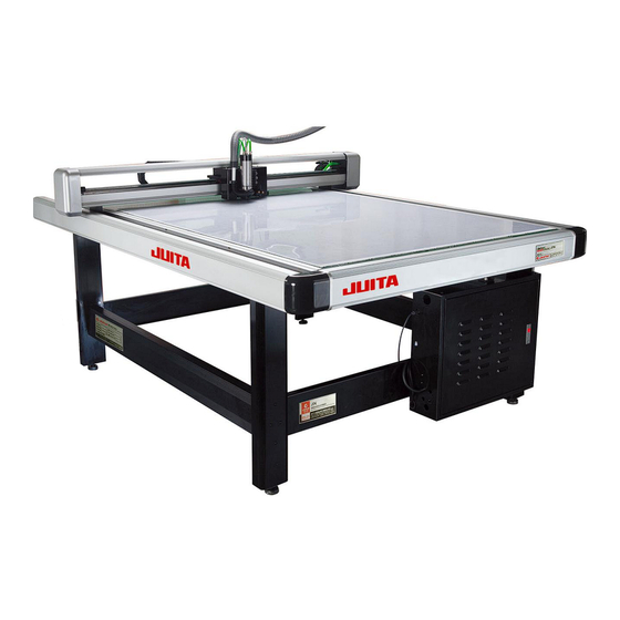
- Page 1 JT-1512B Garment Template Cutting Machine (USER MANUAL) Microsoft is a U.S. registered trademark of Microsoft Corporation. Windows is a registered trademark of Microsoft Corporation Attention: read this manual please, when using this product...
- Page 2 Preface Thanks for choosing the JUITA Template Cutting Machine. The JUITA enjoys not only the beautiful design but also the high precision, strong compatibility, which can operate with the CAD of HPGL. Besides, it operates fast and stable. Before using this template cutting machine, you’d better read this manual to make sure that you will work with it effectively.
-
Page 3: Chapter 1. Safety Notice
Chapter 1. Safety Notice Safety notice: before using this template cutting machine, please read the following instructions: 1. The template cutting machine should be installed horizontally. If the template cutting machine is in uneven status, it cannot work normally. 2. After installation, you should adjust the height of stand until the machine is in a horizontal state. - Page 4 4. The plug should be connected to the panel with the ground wire. Don’t move out plug’s needle. If the machine is not connected with the ground wire, the ESD will harm the human body and damage the parts of the machine. 5.
-
Page 5: Application Notice
Model Product Series Number of the product Please check whether the voltage of AC power corresponds to the marked voltage on the label. Chapter 2. Application Notice Whether you are familiar with the template cutting machine for garment template or not, please read the following application notice: 2.1 application condition (1)The operating temperature range of o Celsius to 35 Celsius. - Page 6 2.2 other notices: (1) Don’t move the GTCM’s holder by hand, otherwise the GTCM may be damaged. (2) Except take on or off the GTCM, don’t screw the fixed nuts on the holder. (3) Don’t add lubricant into the , otherwise the machine may not operate very well.
-
Page 7: Chapter 3. Introduction
Chapter 3. Introduction 3.1 Introduction The garment template cutting machine mainly deals with the cutlery of the complicated graphs or words. With high precision and stability, it enjoys beautiful design. Except that, it is also easily to control with. Specification Material : Nonmetal;... - Page 8 Power Supply:170V/250v 50-60H 300W(max) 3.2 requirement of the software and hardware: The CAD/CAM software should be compatible with the HP-GL : Select the software that support the HP-GL;special format can be ordered; Hardware:Better than the minimum of the mainstream computer 3.3 consumptive materials Tools:milling tools of 2—4MM 、special cutting tools Material: PVC sheet、...
-
Page 9: Chapter 4. Installation
Chapter 4. Installation 4.1 The items included in the packing of the machine: 1、machine table 1 □ 2、lateral stand 2 □ 3、support beam 4 □ 4、power cable 1 □ 5、signal cable 1 □ 6、roll paper bar 1 □ 7、cutter holder 1、pen holder 1 □... - Page 11 (1) firstly, installing the support beam and the two lateral stand. (2) after fixing the whole support, put the machine table on the support and tighten the screw. (3) using the leveller for testing whether the machine table is horizontal. Install paper:...
- Page 12 (3) The spindle motor shall be put on the spindle case carefully which is on the lowest position, in order to let the point of milling cutter be in the same horizontal plane with the limit device. Then, the spindle motor should be tightened by the screw.
- Page 13 (4) After that, according to the thickness of sheet, filling the options in the MarkCad. Remark: Because the error on the height of the spindle motor is introduced after the changing of milling tool, this error should be calculated before working. The calculation method is stated as follows: 1.
- Page 14 you fill in the Mark cad. 4. If the sheet thickness is 0.8 in the Mark Cad by 1MM, the error is 0.2. Then you should minus 0.2 from the sheet thickness which you use in your work when you change the sheet of the different thickness. 5.
- Page 15 decompress Opening folder, will . Then you send it to the desktop as shortcut. (2) Switching on the template machine, the computer and the plotter will begin to initiate the connection……(as the following picture shows) Notice: on the right and the bottom of the monitor, there is a notice for a new disk, and the following dialog box appears.
- Page 16 Select then click BROWSE(as following picture) The driver track of the milling plotter is : C:\平台切割绘图机闪电- V2.0\Driver\ OK, then click select NEXT (as the 确定 following picture shows)
- Page 17 remain the original option,click NEXT(as the following picture shows) At the end, click 完 成 OK, finish the installation of the new disk. Then, open , the following picture will appear: Click “YES”, it will synchronize with the original adjusted parameter. 4.7 Switch on the machine...
-
Page 18: Chapter 5. Software
Firstly release the red button, and then press the green one in the middle: 主电源按钮: Main power supply button 启动按钮: Start Button 风机按钮:Fan Button Chapter 5. Software 5.1 Information for the interface of software (ATTENTION: before opening the software, you should connect the computer to the machine and make sure the machine is power on, otherwise the software cannot be opened.) - Page 19 (1) menu bar: this includes the settings for the main functions of the software (2) Tool bar: (2.1) If you press this button, the mapping file from the other folder except the acquiescent folder of the software will be copied in to that acquiescent folder, and appear on the file list.
- Page 20 2) find your folder that has the mapping file and select the file that you want to draw or cut. 3) click” OPEN”, if it operates well, the system will appear such instructions 4) at this time, the input file will be on the bottom of the listed file.
- Page 21 (2.10) click this button, you will stop the milling. (2.11) click this button, there are lots of tools that you can use for your manual milling. (2.12) click this button, the milling line will change into the half cutting line. (2.13) clicking this button will cancel the half cutting.
- Page 22 (1) Choose of the plan: select the operating way and click the loading. cutting the pattern Cutting plan drawing and cutting Cutting and drawing plan drawing and milling Cutting and milling plan drawing lines Drawing plan milling Milling plan (2)setting the basic parameter;setting the background...
- Page 23 print catalog:the folder that includes the file for using; (1) name of the file:the format of the file that is for using; (2) ending process mod:the process mod after the working. (3) (2)setting basic parameter;working range...
- Page 24 The working range is stetted on the reference of the position of the penholder (1)X working beginning point: Beginning point of the directions of the machine from the left to the right (2)X working ending point: Ending point of the directions of the machine from the left to the right (3)Y working beginning point: the beginning point from ahead of the machine.
- Page 25 The above number is based on the X as the left-right directions, Y as the ahead-behind directions. (1) Precision correction: the correcting the drawing error. X direction: if error is in the X direction, just revise the measured value. Y direction: if error is in the Y direction, just revise the measured value. (2)the deviation between cutter and the pen: the correction number, at this point, the pen and the cutter will coincide.
- Page 26 Error in Y, the left and right will not coincide, just increase or decrease the number. (4)the symmetrical proofread: the correction of the verticality Measuring method: drawing a square of 1-meter circumference, and fill the measured value Correction 1: measuring the value from the left-bottom of the square to its –right-bottom.
- Page 27 ( 2 ) Plan management ; cutting and drawing pattern : after adjusting the parameter, just save the picture and then switch to the present plan. The speed and stress during drawing: the speed of motor and the (1) press of drawing when the machine is drawing lines.(When the picture is unclear, check the voltage.) drawing the cut line: drawing in line with the one that the cutter has (2)...
- Page 28 attunement to the output, the cutting line length is a wire length. The adhesion is the length of the middle connecting point. angle compensation: cutting completely and precisely, (5) cutting order:according to the CAD software; (6) setting of the cutting paper:the beginning point is on the right side (7)...
- Page 29 picture and then switch to the present plan. The speed and stress during drawing: the speed of motor and the (1) press of drawing when the machine is drawing lines.(when the picture is unclear, check the voltage.) drawing the cut line: drawing in line with the one that the cutter has (2)...
- Page 30 more cutting delay, the slower starting to cut); Cutting pressure: the level of pressure when cutting (the bigger pressure for cutting, the greater the sound when cutting) The turn-back distance setting: the setup of distance for turning back (6) one more time after the start of feeding; Chapter6.
- Page 31 Before using has to be opened. using method:click ;putthe sample window behind the working window. click , select the line and then choose the processing tools: using milling cutter; cutting semi knife drawing line; using milling cutter (on the line) using milling cutter (outside the line);...
- Page 32 Setting the parameter intervals between cloth pieces:the length between cloth pieces; (1) diameter of the cutter:the diameter of the milling cutter; (2) input track:the way that receives the file of CAD system (3) output track:after setting the type, the way sending it to the (4)...
- Page 33 Correcting the proportion (1)cutting proportion:the error between the actual data and the measured value can be corrected; Working range setting...
- Page 34 (1)setting the working range:setting the working window according to the cutting materials in the typesetting system.( the switch button on the left side of the machine) setting method: setting by the direction key of the telecontroler and the value you filed in. (2)X working beginning point:right side of the machine(set by pen holder)...
- Page 35 Chapter 7: Common Troubles and Relevant Solutions When you use this machine, if you meet difficulties, please read the following solutions, if you have no idea about solutions, don’t take on or off the parts by yourself. no operation after powering on (1) The machine is not connected to the power.
- Page 36 7.6 Protect of the cutting mat (surface of cutting table): Cutting mat(surface of cutting table) is consumable item and need replace after using year or months depend on the duty of the daily work. Cutting the common paper board you just put the paper board on the cutting mat(surface of cutting table) then you can cut directly.
Need help?
Do you have a question about the JT-1512B and is the answer not in the manual?
Questions and answers