Table of Contents
Advertisement
Quick Links
EV_MOD_CH101 Evaluation Module User Guide
Chirp Microsystems reserves the right to change
specifications and information herein without notice.
Chirp Microsystems
2560 Ninth Street, Ste 200, Berkeley, CA 94710 U.S.A
+1(510) 640–8155
www.chirpmicro.com
AN-000231
Document Number: AN-000231
Revision: 1.0
Release Date: 08/18/2020
Advertisement
Table of Contents

Related Manuals for TDK EV MOD CH101

Summary of Contents for TDK EV MOD CH101
- Page 1 AN-000231 EV_MOD_CH101 Evaluation Module User Guide Chirp Microsystems Document Number: AN-000231 Chirp Microsystems reserves the right to change 2560 Ninth Street, Ste 200, Berkeley, CA 94710 U.S.A Revision: 1.0 specifications and information herein without notice. +1(510) 640–8155 Release Date: 08/18/2020 www.chirpmicro.com...
-
Page 2: Table Of Contents
AN-000231 TABLE OF CONTENTS Scope and Purpose ..................................... 3 EV_MOD_CH101 Evaluation Module Board ............................4 Pin Assignments ..................................4 Electrical Specifications ................................4 Schematic ....................................4 Bill of Materials ..................................5 Configuration, Programming, and Operation ............................ 6 Configuration and Programming ..............................6 Operation .................................... -
Page 3: Scope And Purpose
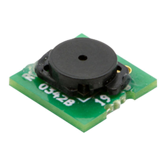
AN-000231 1 SCOPE AND PURPOSE This document details the specification, programming and operation of an EV_MOD_CH101-03-01 (referred to as the EV_MOD_CH101 in the remainder of this document) ultrasonic sensor evaluation module. The module board incorporates a CH101 Ultrasonic Sensor device with an omnidirectional acoustic housing assembly, a capacitor and an FPC/FFC connector. This evaluation module can perform pitch-catch and pulse-echo range-finding at distances from 4 cm to 1.2m. -
Page 4: Ev_Mod_Ch101 Evaluation Module Board
AN-000231 2 EV_MOD_CH101 EVALUATION MODULE BOARD PIN ASSIGNMENTS NAME DESCRIPTION Interrupt output. Can be switched to input for triggering and calibration functions SCL Input. I C clock input. This pin must be pulled up to VDD externally. SDA Input/Output. I C data I/O. -
Page 5: Bill Of Materials
AN-000231 Figure 3. EV_MOD_CH101 Module Connection (EV_MOD_CH101 acoustic port is facing down) FLAT CABLE CONNECTOR TYPE Molex 503480-0800 RECOMMENDED FLAT CABLE Molex 151660073...151660094 Table 2. Recommended Flat Flex Cable and Connector BILL OF MATERIALS QUANTITY REFERENCE PART PCB FOOTPRINT MANUFACTURER MANUFACTURER PART NUMBER CH101-03... -
Page 6: Configuration, Programming, And Operation
AN-000231 3 CONFIGURATION, PROGRAMMING, AND OPERATION Please refer to DS-000379 CH101 Datasheet for information on the device’s electrical characteristics. CONFIGURATION AND PROGRAMMING Please refer to the following documents for configuration and programming information: AN-000154 SmartSonic Hello Chirp Hands-On Document • AN-000175 SonicLib Programmers Guide •... -
Page 7: Mechanical Specifications
AN-000231 4 MECHANICAL SPECIFICATIONS DIMENSION EV_MOD_CH101 UNIT Acoustic port hole Maximum width 8.15 Module height 3.57 Table 4. Geometric Dimensions for EV_MOD_CH101 The outer dimensions of the EV_MOD_CH101 assembly are shown in Figure 4. The acoustic port hole has a diameter of 0.7 mm and is in the center of the front face. -
Page 8: Sensor Mounting And Beam Patterns
AN-000231 5 SENSOR MOUNTING AND BEAM PATTERNS SENSOR MOUNTING To achieve the best acoustic performance, users are recommended to mount the EV_MOD_CH101 module in a flat mounting plate. An example mounting plate is shown in Figure 5, where the sensor has been inserted into a 5.3 mm diameter hole has been drilled in a 1 mm thick plastic plate measuring 135 mm x 175 mm. -
Page 9: Figure 7. Beam Pattern Measurements Of An Ev_Mod_Ch101 (W/O A Mounting Plate)
AN-000231 For comparison, the pulse-echo beam-pattern plot measured for an EV_MOD_CH101 when tested without a sensor mounting plate is shown in Figure 7. The beam pattern has three lobes: a main lobe and two side-lobes that are centered at ±45°. The sensor device will work well for detecting on-axis targets, but targets located at ±25°... -
Page 10: Revision History
©2020 Chirp Microsystems. All rights reserved. Chirp Microsystems and the Chirp Microsystems logo are trademarks of Chirp Microsystems, Inc. The TDK logo is a trademark of TDK Corporation. Other company and product names may be trademarks of the respective companies with which they are associated.
Need help?
Do you have a question about the EV MOD CH101 and is the answer not in the manual?
Questions and answers