
Summary of Contents for Volair Sim SIM UNIVERSAL FLIGHT
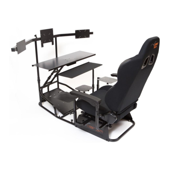
- Page 1 VOLAIR SIM UNIVERSAL FLIGHT|RACING SIM CHASSIS P/N: VS-01-2B ASSEMBLY INSTRUCTIONS Rev. 1.7 © Volair Sim. All Rights Reserved.
- Page 2 Thank you for purchasing the Volair Sim Universal Flight | Racing Sim Chassis! We hope that it will give you countless hours of enjoyment. Although we have designed the system with ease of assembly in-mind, please read these instructions carefully first.
-
Page 3: Installation Drawing
INSTALLATION DRAWING Page... - Page 4 STEP 1: ATTACHING MONITOR BASE TO SEAT BASE Begin assembly by attaching the monitor base to the seat base using the adjustment tubular connectors as shown in FIGURE 1 below. The inner adjustment tubes allow you to vary the distance between the seat base and the monitor base.
- Page 5 TWO (2) M8*16MM SOCKET CAP MACHINE SCREWS (NO. 3) FOUR (4) M6*25MM BUTTON HEAD MACHINE SCREWS (NO. 1) (PRE-INSTALLED) FOUR (4) M6*30 MM BUTTON FOUR (4) M6 SELF-LOCKING NUTS (NO. 4) HEAD MACHINE SCREWS (NO. 2) FIGURE 2B: MONITOR SUPPORT BASE WITH PEDAL TRAY STEP 3: CENTER MONITOR SUPPORT Attach center monitor support to monitor base as shown in FIGURE 3.
- Page 6 Ensure that the row of holes drilled along the top edge of the table is facing towards the seat. These holes are pre-drilled for attaching the Volair Sim Avionics Panel, Logitech (Saitek) Pro Flight Yoke, Logitech Steering Wheel, Thrustmaster T500RS Steering Wheel, and Logitech (Saitek) Pro Flight Accessories (on left and right sides of the yoke) to table.
- Page 7 STEP 5: ATTACHING AVIONICS | WORK TABLE TO MONITOR BASE Attach the assembled table and support structure to the monitor base and tighten the plastic adjustment plastic nuts (circled) lightly as shown in FIGURE 5. You will be able to adjust the distance and angle of the table to suit your preferences after the entire assembly process is complete.
- Page 8 STEP 7: SEAT SUPPORT ASSEMBLY Continue the assembly of the seat base as shown in FIGURE 7 with the two cross braces (#1) and the left (#2), center (#3) and right (#4) square tubes. Note that the seat support brackets attach to the OUTERMOST holes on the two cross braces and that the open square profiles on the cross braces point towards the floor.
- Page 9 STEP 8: SEAT ASSEMBLY Attach the two seat sliders to the seat base using four (4) M8*35mm Socket Cap Machine Screws (No. 6), and four (4) M8 Flange Nuts (No. 8) as shown in FIGURE 8A. Remember to place four (4) M8 silver-colored washers (No. 20) between the bottom of sliders and top of the seat support brackets.
- Page 10 FIGURE 8B: ATTACHING THE SEAT TO SEAT SLIDERS FIGURE 8C: SEAT SPACER (NO. 18) POSITIONING BETWEEN THE SEAT AND SEAT SLIDER Page...
- Page 11 STEP 9: SIDE AND CENTER MOUNT ASSEMBLY Assemble the left and right side-mounts as shown in FIGURE 9A below. Use M8*16mm Machine Screws with Knobs (No. 5) to tighten the support plates to the L-shaped supports. Next, assemble the center stick mount per FIGURE 9C. Use FIGURE 9D to visualize the completed orientation of the left, center, and right mounts.
- Page 12 M8*16MM M8*20MM MACHINE MACHINE SCREW WITH KNOB SCREW WITH KNOB M8*16MM MACHINE SCREW WITH KNOB FIGURE 9C: CENTER MOUNT 1. Joystick mounting plate with M8*16mm Machine Screw with Knob 2. Right angle support tube 3. Vertical tube with M8*20mm Machine Screw with Knob 4.
- Page 13 M4 Washers (No. 10) or suitable machine screws as needed (your display may require larger or longer screws than provided). The Volair Sim cockpit mounts are pre-drilled with the industry standard VESA bolt patterns for most of the common monitor bolt pattern sizes (see below).
- Page 14 STEP 11: KEYBOARD TRAY ASSEMBLY Attach keyboard tray to the keyboard support structure as shown in FIGURE 11. First, apply some of the enclosed silicon grease between the two sliding parts of the keyboard tray and the keyboard post. Next, place the keyboard on the keyboard support post.
- Page 15 STEP 12: ATTACHING ACCESSORIES You have several options when attaching accessories to the Volair Sim chassis. You can opt for a permanent installation using the pre-drilled locations or a semi-permanent installation using the clamps provided with the yoke, steering wheel, and associated accessories.
- Page 16 5. Additional Volair Sim Accessories Volair Sim offers several accessories (sold separately) for your Volair Sim cockpit. The armrests attach to your Volair Sim cockpit allowing greater precision and comfort, especially when flying with the side stick or a HOTAS system. The Volair Sim Avionics Panel (available in “steam gauge”...
Need help?
Do you have a question about the SIM UNIVERSAL FLIGHT and is the answer not in the manual?
Questions and answers