
Related Manuals for Tapco Adaptive Alpha Premier


Summary of Contents for Tapco Adaptive Alpha Premier
- Page 1 Installation and Maintenance Manual Alpha Premier Information Display 1260600601 R UMBER...
- Page 2 © Copyright 2020 Adaptive Display Systems LLC. All rights reserved. Adaptive Display Systems 7840 North 86th Street Milwaukee, WI 53224 USA 414-357-2020 414-357-2029 (fax) http://www.adaptivedisplays.com Adaptive is a registered trademark of Adaptive Display Systems. Alpha Premier Information Display is a registered trade- mark of Adaptive Display Systems.
-
Page 3: Table Of Contents
INTRODUCTION Purpose ............................1-1 Revision history .......................... 1-1 Safety information ........................1-1 Equipment protection ........................1-2 Supplier's Declaration of Conformity ................... 1-2 EQUIPMENT DESCRIPTION Exterior views ..........................2-1 Opening a sign ..........................2-3 Interior views ..........................2-5 Label locations ..........................2-7 MECHANICAL INSTALLATION Overview ............................. - Page 4 THIS PAGE INTENTIONALLY BLANK PID S (PN 1260600601 R . B) LPHA NSTALLATION AND AINTENANCE ANUAL...
-
Page 5: Introduction
Introduction Purpose This manual explains how to mount and electrically connect an Alpha PID sign. It is intended for sign installers. Revision history Revision Date Notes 1260600601 Rev. A November 3, 2020 First release. Safety information Equipment symbols Chassis ground Main power (I = ON, 0 = OFF) Dangers, warnings, cautions, and notices... -
Page 6: Equipment Protection
QUIPMENT PROTECTION Equipment protection Preventing electrostatic discharge (ESD) This equipment contains components that may be damaged by “static electricity”, or electrostatic discharge. To prevent this from happening, be sure to follow the guidelines in Adaptive Display System’s Tech Memo 00-0005, “Preventing Electrostatic Discharge (ESD) Damage,”... -
Page 7: Equipment Description
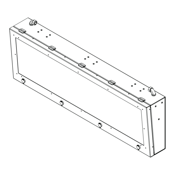
Equipment Description Equip ment Description Exterior views Top Power / Data Entry Top view Single-sided signs Double-sided signs Front and side views All sizes are similar. Single-sided signs Double-sided signs Item Name Description POWER ENTRY Entry point for power wiring COMMUNICATION ENTRY Entry point for communication cables TAMPER PROOF DOOR LATCH... - Page 8 Equipment Description Equip ment Description Exterior views Bottom Power / Data Entry Bottom view Single-sided signs Double-sided signs Front and side views All sizes are similar. Single-sided signs Double-sided signs Item Name Description POWER ENTRY Entry point for power wiring COMMUNICATION ENTRY Entry point for communication cables TAMPER PROOF DOOR LATCH...
-
Page 9: Opening A Sign
PENING A SIGN Opening a sign Tools you will need • Latch key • #2 Phillips screwdriver Hazardous voltage. Contact with high voltage will cause death or serious injury. DANGER The power switches on the circuit breaker DO NOT turn off power to all lines in a sign. Remove power at the source. Blunt Force Trauma. - Page 10 PENING A SIGN Before opening the last door latch, place one hand on the front of the sign case to control the force at which at sign opens. Lower the display board rail. Locate the screws securing the inner display board panel. Use a #2 Phillips screwdriver to loosen the captive screws.
-
Page 11: Interior Views
NTERIOR VIEWS Interior views Primary sign Item Name Description EARTH GROUND LUG It is the end user’s responsibility to make this connection to the sign in accordance to the National Electrical Code (NEC) Article 250 and local codes. This connection is mandatory to ensure compliance with Adaptive warranty. - Page 12 NTERIOR VIEWS Secondary sign Item Name Description 4.2 VDC POWER SUPPLY Supplies power to the display boards CIRCULATING FAN Circulates air within the sign to cool the components LIGHT SENSOR Monitors ambient light and adjusts the sign brightness accordingly DISPLAY ADAPTER Feeds video to the display boards DISPLAY BOARD Displays messages...
-
Page 13: Label Locations
Label locations Sign rating label Adaptive Micro Systems LLC 7840 N. 86th Street Milwaukee, WI 53224 USA SIGN MODEL#: ALPHA PID-8RGB 48RX192C SF * A L P H A P I D - 8 R G B 4 8 R X 1 9 2 C S F * S/N: LW00002014 * L W 0 0 0 0 2 0 1 4 * SERIES: A... -
Page 14: Mechanical Installation
Mechanical Installation Mechan ical Installation Overview The sign must be installed onto a super-structure designed to withstand live loads and comply with all national and local codes. Live loads include loading from wind and seismic events. Because every sign installation is unique, there is no single procedure for mounting. -
Page 15: Sign Mounting Guidelines And Requirements
IGN MOUNTING GUIDELINES AND REQUIREMENTS Sign mounting guidelines and requirements Notice: Do not use the sign’s ground-lug for grounding installation equipment such as welding equipment or the warranty will be void. Only the sign sub-structure may be welded. Welding any other part of the sign, will void the warranty. The method used to mount signs varies greatly from location to location. -
Page 16: Ventilation Requirements
ENTILATION REQUIREMENTS Ventilation requirements Notice: Inadequate ventilation will ultimately result in component failure that may not be covered under warranty. Signs require obstruction-free space for adequate air ventilation between solid mounting surfaces and the top, bottom, and sides of the sign. -
Page 17: Lifting The Sign
IFTING THE SIGN Lifting the sign Crush hazard. Improperly lifting of a sign can create a crush hazard causing personal injury and damage to WARNING WARNING the sign. Do not use eyebolts to lift an assembled sign. They are designed to only lift a sign section from the shipping container. -
Page 18: Mounting The Sign
OUNTING THE SIGN Mounting the sign The methods used to mount a sign vary greatly. It is the installer’s responsibility to ensure that the installation complies with all national and local codes. Notice: Dissimilar metals must be isolated to avoid galvanic corrosion. Any area on the sign’s frame from which paint is removed during mounting, must be recoated with paint that is UL recognized to standard UL-1332, category DTOV2. - Page 19 OUNTING THE SIGN Bracket ceiling mounting (optional) Tools you will need • 7/16-inch socket or wrench Install the brackets using the provided hardware as shown below. Wall mounting Tools you will need • 7/16-inch socket or wrench Install the mounting brackets using the provided hardware as shown below. PID S (PN 1260600601 R .
-
Page 20: Install The Sun Shield (Optional)
NSTALL THE SUN SHIELD OPTIONAL Install the sun shield (optional) Tools you will need • 7/16-inch socket or wrench Install the sun shield using the supplied hardware as shown below. PID S (PN 1260600601 R . B) LPHA NSTALLATION AND AINTENANCE ANUAL... - Page 21 THIS PAGE INTENTIONALLY BLANK PID S (PN 1260600601 R . B) LPHA NSTALLATION AND AINTENANCE ANUAL...
-
Page 22: Electrical Installation
Electrical Installation Electrical Installation Requirements for electrical installation Hazardous voltage. Contact with high voltage will cause death or serious injury. The power switches on the circuit DANGER breaker DO NOT turn off power to all lines in a sign. Remove power at the source. Notice: The following electrical installation requirements must be followed or the sign warranty will be voided. -
Page 23: Earth-Grounding Signs
ARTH GROUNDING SIGNS Earth-grounding signs Properly grounding each sign is necessary because it is an essential means of preventing shock, shock hazards, and potential fire hazards. Failure to properly ground the sign could result in elevated voltage from lightning entering the sign seeking a path WARNING to earth. -
Page 24: Install Power To The Sign
NSTALL POWER TO THE SIGN Install power to the sign Run power to the sign using weather-tight conduit. Connect each power circuit to the appropriate wireway power terminal on the power plate. Circuit breaker/power switch Line Customer connection points Neutral Ground Connect a minimum of one grounding lug to an earth-ground rod. - Page 25 THIS PAGE INTENTIONALLY BLANK PID S (PN 1260600601 R . B) LPHA NSTALLATION AND AINTENANCE ANUAL...
-
Page 26: Networking
Networking Connect to the messaging computer In order to display messages, a sign must be connected to a computer that is running AlphaNET software or other software compatible with the player installed on the controller. This computer is referred to as the messaging computer. The messaging computer is not supplied by Adaptive. - Page 27 THIS PAGE INTENTIONALLY BLANK PID S (PN 1260600601 R . B) LPHA NSTALLATION AND AINTENANCE ANUAL...
-
Page 28: Maintenance
Maintenance Procedure Page Physical inspection Front lens cleaning (outside of sign) Turn off power. Replace the circuit breaker. Replace the surge suppressor. Replace the Ethernet device. Replace the Ethernet to fiber optic converter. Replace the light sensor assembly. Replace the 4.2VDC power supply. 6-10 Replace the 5VDC power supply. -
Page 29: Front Lens Cleaning (Outside Of Sign)
RONT LENS CLEANING OUTSIDE OF SIGN Front lens cleaning (outside of sign) Required materials • Mild, nonabrasive liquid detergent or liquid glass cleaner. Note: Do not use solvents. Use of solvents will damage the lens UV stabilizer. • Soft cloth or soft paper towels. Cleaning procedure Spray the glass cleaner onto the front lens of the sign. -
Page 30: Turn Off Power
URN OFF POWER Turn off power Open the sign. Locate the circuit breaker. There is one circuit breaker in the sign. Position the switch to the OFF position. PID S (PN 1260600601 R . B) LPHA NSTALLATION AND AINTENANCE ANUAL... -
Page 31: Replace The Circuit Breaker
EPLACE THE CIRCUIT BREAKER Replace the circuit breaker Tools you will need • Phillips screwdriver Turn off power. For instructions, see “Turn off power” on page 6-3. Loosen the two screws on the circuit breaker. Disconnect the wires. Loosen Loosen Pull the circuit breaker toward you and lightly twist it to pop it off of the rail. -
Page 32: Replace The Surge Suppressor
EPLACE THE SURGE SUPPRESSOR Replace the surge suppressor Tools you will need • Phillips screwdriver Turn off power. For instructions, see “Turn off power” on page 6-3. Locate the surge suppressor. There is only one surge suppressor. It is located in the primary sign. Loose the two screws on the surge suppressor. -
Page 33: Replace The Ethernet Device
EPLACE THE THERNET DEVICE Replace the Ethernet device Turn off power. For instructions, see “Turn off power” on page 6-3. Locate the device. There is only one Ethernet device. It is located in the primary sign. Disconnect the connections. Remove the device. -
Page 34: Replace The Ethernet To Fiber Optic Converter
EPLACE THE THERNET TO FIBER OPTIC CONVERTER Replace the Ethernet to fiber optic converter Turn off power. For instructions, see “Turn off power” on page 6-3, Locate the device. There is only one Ethernet to fiber optic converter. It is located in the primary sign. Disconnect the cables. -
Page 35: Replace The Light Sensor Assembly
EPLACE THE LIGHT SENSOR ASSEMBLY Replace the light sensor assembly Tools you will need • Phillips screwdriver Turn off power. For instructions, see “Turn off power” on page 6-3. Locate the device. For two-sided signs th,ere is a light sensor on each side of the sign. Remove the two screws. -
Page 36: Replace The 4.2Vdc Power Supply
4.2VDC EPLACE THE POWER SUPPLY Replace the 4.2VDC power supply Tools you will need • Phillips screwdriver • 3/8 inch socket or wrench Turn off power. For instructions, see “Turn off power” on page 6-3. Locate the power supply. Two-sided signs contain power supplies in each side of the sign. Disconnect the cables and remove the nuts. -
Page 37: Replace The 5Vdc Power Supply
5VDC EPLACE THE POWER SUPPLY Replace the 5VDC power supply Tools you will need • Phillips screwdriver Turn off power. For instructions, see “Turn off power” on page 6-3. Locate the power supply. There is one 5VDC power supply. It is located in the primary sign. Use your finger or a small screw driver to press the tab to release the power supply from the rail. -
Page 38: Replace The Display Adapter Board
EPLACE THE DISPLAY ADAPTER BOARD Replace the display adapter board Tools you will need • #2 Phillips screwdriver Turn off power. For instructions, see “Turn off power” on page 6-3. Locate the display adapter. Disconnect all cables from the display adapter and remove the six mounting screws. Notice: Carefully and slowly disconnect the cables. -
Page 39: Replace The Sign Controller
EPLACE THE SIGN CONTROLLER Replace the sign controller Tools you will need • #2 Phillips screwdriver Turn off power. For instructions, see “Turn off power” on page 6-3. Locate the sign controller. The controller is always located in the primary sign. Disconnect all cables from the display adapter and remove the 6 mounting screws. -
Page 40: Replace The Fan
EPLACE THE FAN Replace the fan Tools you will need • 3/8 inch socket or wrench Turn off power. For instructions, see “Turn off power” on page 6-3. Locate the fan. Remove the nuts that secure the fan bracket to the sign enclosure. Remove these nuts. -
Page 41: Replace The Display Board
EPLACE THE DISPLAY BOARD Replace the display board Tools you will need • Socket wrench and 7/32 inch socket Turn off power. For instructions, see “Turn off power” on page 6-3. Locate the display board. Remove the six screws and disconnect the cables. Notice: Carefully and slowly disconnect the cables. - Page 42 THIS PAGE INTENTIONALLY BLANK...
- Page 43 • • 1260600601 R UMBER Adaptive Display Systems 7840 North 86th Street Milwaukee, WI 53224 USA 414.357.2020 www.AdaptiveDisplays.com...
Need help?
Do you have a question about the Adaptive Alpha Premier and is the answer not in the manual?
Questions and answers