Advertisement
W/SC420
W/SC420
W/SC420
W/SC420- - - - 915
Wireless Transceiver with an Interface for 4-20mA
Current Loop Sensor
1. INTRODUCTION
1. INTRODUCTION
1. INTRODUCTION
1. INTRODUCTION
The W/SC420-915 is a two-way wireless transceiver with an embedded interface for the very robust and
popular 4-20mA current loop sensor signaling standard.
The device wakes up periodically, according with the programmed 'Reporting Period' (see
Configuring the Device
and also check the 'Wireless Control Panel Operating Instruction' manual) and
switches ON an embedded power source having a nominal voltage rate of 16V to feed an attached 4-
20mA current loop sensor. The device then waits a 'Stabilization' time, as programmed (see
Configuring the Device
and also check the 'Wireless Control Panel Operating Instruction' manual), and
when this time expires, it samples the loop's current using an embedded, high resolution, 24 bits wide
ADC.
The sampled current is then transmitted to a Wireless Control Panel for further processing, reporting
and storage. Check the 'Wireless Control Panel Operating Instruction' for more information.
Operating power is obtained from two on-board 3V Lithium batteries. When the battery voltage is low, a
"low battery" message is sent to the Control Panel.
Caution!
Risk of explosion if battery is replaced by an incorrect type. Dispose of used battery according to
manufacturer's instructions.
2 2 2 2 . INSTALLATION
. INSTALLATION
. INSTALLATION
. INSTALLATION
2.1 Mounting
In order to achieve a good quality of communication link, a good practice is to install the transceiver high as practically possible, mounted on a
wall or a pole, where at least one meter radius of the space in the front of the transceiver box is clear from metallic objects.
It is also advised that the transceiver is not installed in close proximity to electronic equipment such as work stations, routers and or any other
type of radiating equipment.
It is recommended that before the actual mounting of the device in the final installation location, the communication link from the preferred
location is first tested. In order to test the quality of the link, the device must first be enrolled to the control panel (see
recommended to perform the enrollment when standing next the control panel and only then, when the device is enrolled and functional, to
proceed with the field installation as described here.
To test the quality of the link press momentarily the 'Enroll/Test' button (see Figure 2). The red LED starts blinking slowly, while all possible
routes to the control panel are tested. This may take up to 15 seconds. When the test is completed and the best route is selected, the
transceiver flashes shortly the green LED 3 times to indicate that the quality of the link is excellent, both LEDs (green and red) to indicate that the
quality of the link is good or only the red LED to indicate that the quality of the link is poor. If communication cannot be established, no LED is
flashed.
Enroll/Test Button
Figure 2: 'Enroll/Test' Button
W/SC420-915 Installation Instructions
915
915
915
Installation Instructions
2.4.
2.4.
LED Response
3 x green LED flashes
3 x green & red LED flashes
3 x red LED flashes
No flashes
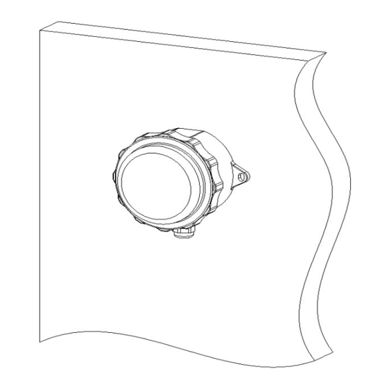
Figure 1: External View
2.2.
Enrollment). Note: It is
Link Quality
Excellent
Good
Poor
No communication
1
Advertisement
Table of Contents

Summary of Contents for SensiNext W/SC420-915
- Page 1 1. INTRODUCTION 1. INTRODUCTION 1. INTRODUCTION The W/SC420-915 is a two-way wireless transceiver with an embedded interface for the very robust and popular 4-20mA current loop sensor signaling standard. The device wakes up periodically, according with the programmed ‘Reporting Period’ (see 2.4.
- Page 2 (i.e. shorter battery life expectancy) Optional settings: 5 ms, 10 ms, 50 ms, 100 ms, 200 ms, 500 ms, 1 s, 2 s, 5 s, 10 s, 15 s, 20 s, 30 s, 60 s, W/SC420-915 Installation Instructions...
- Page 3 For information regarding the recycling of this product you must contact the company from which you orignially purchased it. If you are discarding this product and not returning it for repair then you must ensure that it is returned as identified by your supplier. This product is not to be thrown away with everyday waste. Directive 2002/96/EC Waste Electrical and Electronic Equipment. W/SC420-915 Installation Instructions...
Need help?
Do you have a question about the W/SC420-915 and is the answer not in the manual?
Questions and answers