
Related Manuals for Pego NEXUS S27

Summary of Contents for Pego NEXUS S27
- Page 1 NEXUS S27 Driver for Stepper electronic expansion valve User and maintenance manual ENGLISH READ AND KEEP Rel. 1 REV. 01-23 ELECTRICAL BOARDS FOR REFRIGERATING INSTALLATIONS...
- Page 2 NEXUS S27 Indice OPERATION AND MAINTENANCE MANUAL Page 2 Rev. 01-23...
-
Page 3: Table Of Contents
CONTENTS INTRODUCTION CHAP. 1 Page 3 General Page 3 Product identification codes Page 4 Overall dimensions Page 4 Identification data INSTALLATION CHAP. 2 Page 5 General warnings for the installer Page 5 Mechanical fixing TECHNICAL FEATURES CHAP. 3 Page 6 Technical features WARRANTY TERMS CHAP. -
Page 4: General
NEXUS S27 Indice CHAPTER 1: INTRODUCTION GENERAL DESCRIPTION: The NEXUSS27 is an electronic regulator for controlling the motorized electronic expansion valve, with integrated connectivity functions through the myPego app. It manages the most common motorized electronic expansion valves and integrates evaporator superheat management. - Page 5 CHAP. 2 – Installazione NEXUS S27 OVERALL DIMENSIONS Dimensions in mm. IDENTIFICATION DATA The device described in this manual has a plate on one side bearing the identification data: • Name of Manufacturer • Code and model of the device •...
-
Page 6: Mechanical Fixing
CHAP. 3 – Technical features NEXUS S27 CHAPTER 2: INSTALLATION GENERAL WARNINGS FOR THE INSTALLER 1. Install the appliance in places that respect the degree of protection and keep the box intact as much as possible when drilling the holes for housing the cable glands and/or pipe presses. -
Page 7: Technical Features
CHAP. 2 – Installazione NEXUS S27 CHAPTER 3: TECHNICAL FEATURES TECHNICAL FEATURES Power supply 24 V~ 10% 50-60Hz Main Voltage Auxiliary power supply 24 V dc (dedicated for the backup battery) Max power consumption (electronic control only) Depending on valve, maximum 25VA with ALCO EX8... -
Page 8: Warranty Terms
The intervention service in warranty can be refused when the equipment is modified or transformed. Under no circumstances Pego S.r.l. will be liable for any loss of data and information, costs of goods or substitute services, damage to property, people or animals, loss of sales... -
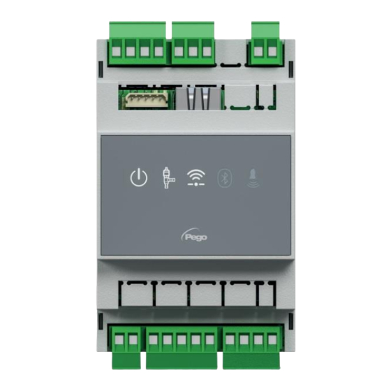
Page 9: Display Description
CHAP. 5 – Data programming NEXUS S27 CHAPTER 5: DATA PROGRAMMING DISPLAY DESCRIPTION ENABLING ICON Led OFF = Enable input OFF (see In1/2/3 configuration) Led ON = Enable input ON (see In1/2/3 configuration) EEV OUTPUT STATUS ICON Led OFF = Motorized valve closed... -
Page 10: Mypego App Interface
NEXUS S27 MYPEGO APP INTERFACE The myPego app is the official Pego application for the control and supervision of NEXUS line instruments. It is available for free on the App Store and Google Play Store. Direct connection to the device via Bluetooth BLE;... - Page 11 CHAP. 5 – Data programming NEXUS S27 Connecting to Cloud Device Choosing the Cloud Connection accesses the tool selection page. Here it is possible to select which of the registered instruments (through the procedure indicated in the previous chapter) it is possible to access to monitor the status of the system.
- Page 12 CHAP. 5 – Data programming NEXUS S27 Enable input Defrost input Valve is open Current superheating Superheating setpoint Adjustment information Output status Input status Menu bar By touching the keys on the bottom bar it’s possible to access the other configuration...
-
Page 13: Connections Setup
CHAP. 5 – Data programming NEXUS S27 - Parameters page Level selection: tap to change parameter level Parameter identifier Parameter description Parameter value: touch to modify (only with cCL=2) - Cloud page Allows configuration connection to the cloud and the network settings (see the Chapter Connections setup). - Page 14 CHAP. 5 – Data programming NEXUS S27 To connect the NEXUS instrument to the internet via Wi-Fi or ethernet, do the following: 1) Download the myPego app from the Google/Apple store and install it on a smartphone/tablet. 2) Activate Bluetooth on the NEXUS instrument with the dedicated activation key. The flashing icon activates.
- Page 15 CHAP. 5 – Data programming NEXUS S27 8) By clicking “Ok” in the previous point, the Login page opens. If already registered, enter the registration e-mail password click Login. Otherwise click "Sign in" to make the first registration. 9) If you are registering for the first time, please enter a valid e-mail address and password.
- Page 16 CHAP. 5 – Data programming NEXUS S27 12) Enter your payment details (only the methods provided available). The charge will take place only after the trial period and it is possible to interrupt the renewal of the subscription at any time.
- Page 17 NEXUS 17) If the Cloud connection was configured (see point 13), after a few moments the icon is activated to signal that the device is correctly sending data to the Pego Cloud. OPERATION AND MAINTENANCE MANUAL Rev. 01-23...
-
Page 18: Instrument Sharing
CHAP. 5 – Data programming NEXUS S27 INSTRUMENT SHARING 5.2.2 The "Instrument Sharing" function allows you to share the NEXUS with other users (up to 3) even if they are not subscribers (it’s sufficient that each user has their own account). -
Page 19: Web Interface / Http Access
= active registrations For further information, refer to the dedicated manual to be requested from Pego. WEB SERVER Type the local IP address of the connected instrument in the address bar of the web browser: the access page appears. Access to the NEXUS homepage is subject to access control using a username and password. - Page 20 CHAP. 5 – Data programming NEXUS S27 The web interface consists of a few fixed sections: ▪ left: page navigation menu. ▪ above: page name, serial number and type of connected user. ▪ right: page content. - Main page Page navigation...
- Page 21 CHAP. 5 – Data programming NEXUS S27 - I/O (Inputs / Outputs) Input/output Input / output description Input/output status terminal PIN (digital or analog) If digital: - green: input / output active - grey: input / output not active If analog, the analog input or output value is displayed.
- Page 22 CHAP. 5 – Data programming NEXUS S27 Increases or decreases Parameter code Parameter description Current value value - Setup On the "Setup” page it’s possible to configure the language of the webserver. - Info OPERATION AND MAINTENANCE MANUAL Page 22...
-
Page 23: Remote Console Interface (Optional)
CHAP. 5 – Data programming NEXUS S27 REMOTE CONSOLE INTERFACE (OPTIONAL) 200NANOTTL01 UP KEY Increase values / Scroll up parameters Silence the audible alarm if present / Acquire an alarm. DOWN KEY Decrease values / Scroll down parameters ... -
Page 24: Remote Console Key Combination (Optional)
CHAP. 5 – Data programming NEXUS S27 "ALARM PRESENT" ICON Led OFF = No alarm present. Led ON = Alarm triggered and then reset. Flashing LED = Alarm present. REMOTE CONSOLE KEY COMBINATION (OPTIONAL) 5.4.2 EXIT PROGRAMMING If pressed simultaneously for more than 3 seconds inside any programming menu, they save the settings made by exiting the menu itself. -
Page 25: Esh Set Point Setting And Display
CHAP. 5 – Data programming NEXUS S27 QUICK VIEW MENU (READ ONLY) If pressed simultaneously for more than 3 seconds, they allow access to the quick display menu. When entering the menu, a confirmation BEEP is generated. Within this menu, the up and down arrows allow you to scroll through the various parameters. - Page 26 CHAP. 5 – Data programming NEXUS S27 1st LEVEL PROGRAMMING (Installer level) Via the myPego app: 1. Open the myPego app and connect to the instrument called "NEXUSS27" via Bluetooth or via cloud. 2. Touch the "Parameters" button in the bottom toolbar.
- Page 27 CHAP. 5 – Data programming NEXUS S27 PAR. MEANING VALUES DEFAULT 1 = (tS4) Probe visualization (S4) Suction temperature. 2 = (tS5) Probe display (S5) Evaporation temperature. Visualization on the main display 3 = (PS5) Probe display (S5) Evaporation pressure.
- Page 28 CHAP. 5 – Data programming NEXUS S27 PAR. MEANING VALUES DEFAULT Via the myPego app: Send the value "291" to restore the default parameters. Setting the default parameters With remote console: Position on the dEF parameter and press all the keys for 10 seconds to restore the default parameters.
- Page 29 CHAP. 5 – Data programming NEXUS S27 PAR. MEANING VALUES DEFAULT 11 = R449A 0 = R404 12 = R290 1 = R134 13 = R32 2 = R22 14 = R448A 3 = R407A 15 = R452A Type of refrigerant GAS used.
- Page 30 CHAP. 5 – Data programming NEXUS S27 PAR. MEANING VALUES DEFAULT Low superheating protection. 0 = LSH protection and relative If enabled, when SH < LSH the PID integration time is LSH alarm signaling disabled. set according to the selection from 1 to 7 of ELS.
- Page 31 CHAP. 5 – Data programming NEXUS S27 PAR. MEANING VALUES DEFAULT threshold (minimum saturated evaporation temperature referred to sensor S5). It represents the minimum evaporation pressure, expressed in saturated degrees, below which the LOP protection is activated. In -45°C ÷ (MOP-1) -45°C...
-
Page 32: Valve Management (Eev Parameter)
CHAP. 5 – Data programming NEXUS S27 Valve management (EEV parameter) 5.9.1 Setting the EEV parameter from 1 to 5 loads the default values in the variables ESH, EPb, EtI, Etd, LSH, ELS, MOP, EMO, LOP, ELO. In this case the controller acts as a superheat regulator, based on the value read by the connected pressure/temperature probes. - Page 33 CHAP. 5 – Data programming NEXUS S27 3rd LEVEL PARAMETERS LIST (Stepper valve parameters) 5.11 PAR. MEANING VALUES DEFAULT -2= Valve disabled -1= Valve not configured 0 = Customized (set EEV parameters) 1 = Carel EXV 2 = Danfoss ETS 25-50...
- Page 34 CHAP. 5 – Data programming NEXUS S27 PAR. MEANING VALUES DEFAULT 0 = disabled Active synchronisation 1 = enabled in opening Each time the valve must be completely opened or 2 = enabled in closure closed, a certain number of steps more is executed to...
-
Page 35: Quick View Menu (Read-Only)
CHAP. 5 – Data programming NEXUS S27 QUICK VIEW MENU (READ-ONLY) 5.12 During the start-up of the system it may be useful to simply check the reading of the various probes or of some values to verify or optimize the process. To access these values: Via the myPego app: 1. -
Page 36: Password Function
EXPORT / IMPORT PARAMETERS 5.18 It’s possible to export / import the parameters set in the NEXUS S27 via the USB port on board. To do this you need the optional remote display. 1. Insert the USB memory into the slot on the electronic board. -
Page 37: Telenet Monitoring/Supervision System
CHAP. 6 – OPTIONS NEXUS S27 CHAPTER 6: OPTIONS TELENET MONITORING/SUPERVISION SYSTEM To connect the electrical panel to a TeleNET network, follow the diagram below. Refer to the TeleNET user manual for instrument configuration. IMPORTANT: During the configuration, under "Module" select "PEV-PULSE Instrument". - Page 38 CHAP. 7 – Diagnostics NEXUS S27 CHAPTER 7: DIAGNOSTICS DIAGNOSTICS In the event of any anomalies, the NEXUS S27 controller warns the operator through alarm codes displayed on the remote display or with notification via the myPego app. CODE POSSIBLE CAUSE OPERATION TO BE PERFORMED •...
- Page 39 THIS DECLARATION OF CONFORMITY IS ISSUED UNDER THE EXCLUSIVE RESPONSIBILITY OF THE MANUFACTURER: PEGO S.r.l. a socio unico - Via Piacentina 6/b, 45030 Occhiobello (RO) – Italy – Società soggetta all’attività di direzione e coordinamento di Castel S.r.l. DENOMINAZIONE DEL PRODOTTO IN OGGETTO / DENOMINATION OF THE PRODUCT IN OBJECT MOD.:...
-
Page 40: Connection Diagram
NEXUS S27 Annexes CONNECTION DIAGRAM OPERATION AND MAINTENANCE MANUAL Page 40 Rev. 01-23... - Page 41 Annexes NEXUS S27 LAYOUT AND DESCRIPTION OF SENSORS Evaporator Condenser Suction Temperature Evaporation Pressure Compressor VALVES CONNECTION Valve (par. tEU) PIN 15 PIN 14 PIN 13 PIN 12 1 = Carel EXV GREEN BROWN YELLOW WHITE 2 = Danfoss ETS 25-50...
- Page 42 NEXUS S27 Annexes NOTES __________________________________________________________________ __________________________________________________________________ __________________________________________________________________ __________________________________________________________________ __________________________________________________________________ __________________________________________________________________ __________________________________________________________________ __________________________________________________________________ __________________________________________________________________ __________________________________________________________________ __________________________________________________________________ __________________________________________________________________ __________________________________________________________________ __________________________________________________________________ __________________________________________________________________ __________________________________________________________________ __________________________________________________________________ __________________________________________________________________ __________________________________________________________________ __________________________________________________________________ __________________________________________________________________ OPERATION AND MAINTENANCE MANUAL Page 42 Rev. 01-23...
- Page 43 Annexes NEXUS S27 NOTES __________________________________________________________________ __________________________________________________________________ __________________________________________________________________ __________________________________________________________________ __________________________________________________________________ __________________________________________________________________ __________________________________________________________________ __________________________________________________________________ __________________________________________________________________ __________________________________________________________________ __________________________________________________________________ __________________________________________________________________ __________________________________________________________________ __________________________________________________________________ __________________________________________________________________ __________________________________________________________________ __________________________________________________________________ __________________________________________________________________ __________________________________________________________________ __________________________________________________________________ __________________________________________________________________ __________________________________________________________________ OPERATION AND MAINTENANCE MANUAL Rev. 01-23 Page 43...
- Page 44 Phone. +39 0425 762906 e-mail: info@pego.it – www.pego.it TECHNICAL ASSISTANCE Phone +39 0425 762906 e-mail: tecnico@pego.it Distributor: PEGO s.r.l. reserves the right to make amendments to this user manual at any moment. OPERATION AND MAINTENANCE MANUAL Page 44 Rev. 01-23...
Need help?
Do you have a question about the NEXUS S27 and is the answer not in the manual?
Questions and answers