Table of Contents
Advertisement
Quick Links
TRANSLATION OF THE ORIGINAL VERSION
Operating Manual
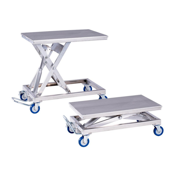
Lightweight Aluminium Scissor Lift Table with Foot-Hydraulics
Type HS 200 | FH
HS 200 | FH
Valid for type:
Reinhold Beck Maschinenbau GmbH
Im Grund 23 | DE -72505 Krauchenwies
Tel.: +49 (0) 7576 / 962 978 - 0 | Fax: +49 (0) 7576 / 962 978 - 90
E-Mail:
info@beck-maschinenbau.de
| Web:
https://www.beck-maschinenbau.de
Advertisement
Table of Contents

Summary of Contents for R. Beck Maschinenbau HS 200 FH
- Page 1 TRANSLATION OF THE ORIGINAL VERSION Operating Manual Lightweight Aluminium Scissor Lift Table with Foot-Hydraulics Type HS 200 | FH HS 200 | FH Valid for type: Reinhold Beck Maschinenbau GmbH Im Grund 23 | DE -72505 Krauchenwies Tel.: +49 (0) 7576 / 962 978 - 0 | Fax: +49 (0) 7576 / 962 978 - 90 E-Mail: info@beck-maschinenbau.de | Web:...
-
Page 2: Table Of Contents
Table of Contents Introduction ................................4 Legal Notice ....................................4 Illustrations ....................................4 Symbols ................................... 4 General Symbols ..................................4 Symbols in Safety Instructions..............................5 General ..................................6 Advantages ....................................6 Applications ....................................6 Target Group and Previous Experience ............................6 Requirements for the Operators .............................. - Page 3 Troubleshooting ..............................18 Maintenance and Repair ............................19 11.1 Safety Catch for Securing ................................19 11.1.1 Replacing the Hydraulic Cylinder ............................. 19 11.2 Maintenance Intervals ................................19 Optional Table Tops ............................... 20 12.1 Table Top AW 100 Smooth ................................. 20 12.2 Table Top Beech Multiplex .................................
-
Page 4: Introduction
1 Introduction The information in this operating manual enables safe, proper and economical operation of your lift table. Please observe all the explanations, notes and regulations • to avoid dangers and malfunctions, • to reduce repair costs and downtimes • and to increase reliability and service life of your lift table. -
Page 5: Symbols In Safety Instructions
Symbols in Safety Instructions The lift table is designed and manufactured according to the current state of the art. Nevertheless, residual hazards may occur during handling. In this operating manual, possible dangers and residual risks are pointed out at appropriate places. Safety instructions are provided with corresponding danger symbols which have the following meanings: Symbol Safety Instruction... -
Page 6: General
3 General The operating manual must be read carefully and understood before handling the lift table! If anything is unclear, please contact the manufacturer. The HS 200 lightweight scissor lift table has been specially designed for use outside the company, for example by service technicians, fitters or craftsmen. -
Page 7: Accident Prevention
Accident Prevention To avoid accidents, the following rules must be observed for operation: Prevent unauthorized persons from gaining access to the lift table. Keep unauthorized persons away from the danger areas. Repeatedly inform present other persons about existing residual risks (see section 4.8 "Residual Risks"). Conduct and record regular training &... -
Page 8: Safety
4 Safety Basic Safety Instructions Lift tables can be dangerous if used improperly. Therefore, observe the safety instructions listed in this chapter and the accident prevention regulations of your employer's liability insurance association! The manufacturer accepts no liability for damage and malfunctions resulting from failure to observe these operating instructions. -
Page 9: Consequences In Case Of Disregard
Consequences in Case of Disregard If the lift table is not operated, maintained or repaired in accordance with the safety regulations, not as intend- ed, improperly or in an abusive manner, the following will result: Dangers to the health of the operating personnel Dangers to the lift table and objects in its vicinity Impairment of the lift table function In case of improper use of the lift table, any warranty, liability and other claims for damages of the operator... -
Page 10: Hazardous Areas
Hazardous Areas Source Area Cause Risk Prevention Foot pump On the foot bar Slipping off the Injuries to feet Keep foot bar for height ad- foot bar and legs and shoes dry justment Wear work shoes with non-slip soles Mechanics Lifting scissor / Crushing and Loss of limbs,... -
Page 11: Residual Risks
Residual Risks The lift table is built according to the latest state of the art and the recognised safety rules. Nevertheless, the use of the lift table may cause danger to life and limb of the user or third parties or damage to the lift table and other equipment. -
Page 12: Organisational Measures
4.10 Organisational Measures Always keep this operating manual within easy reach and at the place of use of the lift table. In addition to the operating manual, observe and instruct on generally applicable legal and other binding regulations for accident prevention and environmental protection. Supplement the operating manual with further instructions, including supervisory and reporting duties, to take account of special operational features (e.g. -
Page 13: Technical Specifications
Technical Specifications Lift Table Type HS 200 FH Article number 180.100.00 Special feature aluminium lightweight construction Standard table top material 3 mm thick aluminium sheet Working platform dimensions 1000 x 600 x 3 mm Total height 1010 mm Effective stroke 610 mm... -
Page 14: Transport To The Installation Site
Transport to the Installation Site Only trained personnel may be used for the following work: • Transport the lift table • Unloading the lift table • Check delivery condition of the lift table Unloading the Lift Table There is an increased risk of accidents when unloading and transporting the lift table! The lift table can fall or tip over due to its weight! Use only suitable and technically perfect lifting gear and suspension systems with an adequate lifting capacity of 500 kg. -
Page 15: Requirements For The Installation Site
Requirements for the Installation Site The following guidelines apply with regard to space requirements, load-bearing capacity and the condition of the substrate: • Space requirements: W x H x D = 1200 x 400 x 700 mm (with standard table top) W x H x D = 1350 x 430 x 820 mm (with optional table top, see ... -
Page 16: Components And Controls
Components and Controls Figure 3: Components and controls Pos. Description Pos. Description Foot bar for height adjustment Lift table platform Swivel castor (4 pieces) Hydraulic cylinder Parking brake (2 pieces) Safety catch for maintenance Lifting scissor Available options and other accessories see chapter 15. BA_BM_HS-200_EN_43-21.docx... -
Page 17: Installation And Commissioning
Installation and Commissioning The lift table must be set up in a stable position so that there are no crushing or shearing points between the lift table and/or the load and objects in the vicinity. Therefore, ensure sufficient space around the lift table. It must be possible to carry out the intended work on the lift table or the load without obstruction. -
Page 18: Height Adjustment
9.3.1 Height Adjustment When adjusting the height, make sure that there are no objects between the scissor construction under the platform and that the safety catch ( 11.1) is unlocked. Be aware of the risk of crushing hands and fingers, especially when positioning downwards. Nev- er reach into the scissors during height adjustment! The height adjustment of the lift table is based on the scissor principle. -
Page 19: Maintenance And Repair
Maintenance and Repair Maintenance and repair work may only be carried out by competent, trained and instructed personnel. If nec- essary, further operating instructions and/or additional documents must be observed. After maintenance or repair work on the lift table, always carry out a function test. •... -
Page 20: Optional Table Tops
Optional Table Tops The characteristics of the table top depend on the work process and the requirements of the working environ- ment. Therefore, three different, attachable table tops are optionally available for individual processing forms and different requirements: 12.1 Table Top AW 100 Smooth •... -
Page 21: Decommissioning
Decommissioning • Before taking out of service, the platform of the lift table must be lowered completely. • For recommissioning, observe chapter 8 “Installation and commissioning “. • For the final scrapping of the lift table, please refer to chapter 14. Disassembly and Scrapping When dismantling and scrapping the lift table, the current EU regulations or the respective regulations and laws of the country of operation, which are prescribed for proper dismantling and disposal, must be observed. -
Page 22: Options And Accessories
Options and Accessories In the following tables you will find options and accessories that you can use to upgrade your lift table. Only use the original accessories and spare parts specified by the manufacturer. The use of other accessories or spare parts may cause injury to persons and damage to the lift table. The manufacturer accepts no liability for any damage resulting from the use of non-prescribed accessories and spare parts or additional components from third parties! 15.1 Table Tops... - Page 23 Continuation “15.1.1 Accessories for Table Top Hole Grid Beech-Multiplex” Article Description Art.-No. VERTICAL RAIL CLAMP The lever handle with latching mechanism offers dosed, fast and 22 x 8.5 mm, vibration-proof tensioning during vertical workpiece clamping. VARIABLE PROJECTION, 200.713.22 Projection = 100 mm | Clamping height max. 200 mm | LEVER HANDLE WITH Swivelling by 360°...
-
Page 24: Eu - Declaration Of Conformity
DE-72505 Krauchenwies (Germany) Phone: 0049 - 7576 962 978 0 Fax: 0049 - 7576 962 978 90 hereby declares that the manufactured machine Model: HS 200 FH Type designation: Lift Table Serial number(s): Year of manufacture: in the version provided complies with the EU Machinery Directive 2006/42/EC and the following...
Need help?
Do you have a question about the HS 200 FH and is the answer not in the manual?
Questions and answers