Advertisement
T o w a r d s C l e a n W a t e r
T o w a r d s C l e a n W a t e r
T o w a r d s C l e a n W a t e r
T o w a r d s C l e a n W a t e r
DOMESTIC
DOMESTIC
WASTEWATER TREATMENT
WASTEWATER
WASTEWATER
TREATMENT
TREATMENT SYSTEM
F
C
UJI
UJI
LEAN
LEAN
Installation
Installation Manual
SYSTEM
ACE
ACE
Manual
Updated: 1 Aug
Aug 2020
Advertisement

Related Manuals for FujiClean ACE

Summary of Contents for FujiClean ACE
- Page 1 T o w a r d s C l e a n W a t e r T o w a r d s C l e a n W a t e r T o w a r d s C l e a n W a t e r T o w a r d s C l e a n W a t e r DOMESTIC DOMESTIC...
-
Page 2: Table Of Contents
WARRANTY & REPAIR POLICY .................. 10 1 SAFETY PRECAUTIONS Read the safety precautions carefully before installing the FujiClean plant. The contents of this section are important to ensure safety. Please pay special attention to the following symbols. Installation must be carried out in accordance with the relevant safety regulations. -
Page 3: Specifications Of The System
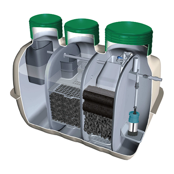
2 SPECIFICATIONS OF THE SYSTEM Aerobic Contact Aeration Pipes Filtration Chamber Pump Chamber Sedimentation Chamber Chlorinator Irrigation Pump S O O S Anaerobic Filtration Chamber Aerobic Contact Horizontal Sectional View Filtration Chamber Recirculation Pipe Inlet Blower Box Access Covers Outlet Riser Ring High Water Level(HWL) ↓... -
Page 4: Installation
3 INSTALLATION STEP 1 SITE PREPARATION Inspect the tank for any damage during transportation. The air blower, parts bag, and the • submersible pump (if ordered) are stored in the anaerobic filtration chamber. The system must be installed away from building foundations and traffic areas so the external •... - Page 5 STEP 4 BACKFILLING – up to the inlet The tank is to be filled with water evenly • Watered and compacted throughout all chambers before any backfill is placed around the system. Make sure all lids are closed before • backfilling.
- Page 6 STEP 5 CONNECTIONS (continued) Blower Pipework Connect to the blower outlet. Connect the blower to the system with • supplied PVC Grey pipes and fittings as shown in the drawing on the right. Glue into the air intake on the tank. Pump Pipework Connect the pump to the outlet with PVC •...
- Page 7 STEP 6 STEP 6 CABLE WORKS CABLE WORKS Plug into the bot Plug into the bottom of the Treatment Monitor Unit Treatment Monitor Unit. Run the power cable for the pump and Run the power cable for the pump and Run the power cable for the pump and Run the power cable for the pump and •...
- Page 8 Close and secure all the three access cover lids with 22 x screws supplied with the system. • STEP 9 OWNER’S MANUAL Pass a hard copy of the FujiClean ACE owner’s manual supplied with the system (included • in the clear parts bag), or email a soft copy to the owner.
-
Page 9: Wiring Instructions For Electrician
All electrical power connections to the system must be carried out by a licensed electrician. The power supply to the FujiClean ACE is single phase service and requires a dedicated circuit protected by a 10A RCD. Connect remote alarm plate to the Treatment Monitor Unit with two wire cable. Since the two wire alarm cable is enclosed in the same conduit as the mains supply to this unit back to the house, the cable must be rated for 240V to comply with the Australian Standard. -
Page 10: Commissioning
5 COMMISSIONING Pre-operational Inspection Inspect and ensure the following requirements are met: The system is accessible and nothing inhibits maintenance. • Surface water is draining away from the system. • The system is filled with water, is level, and each component functions properly. •... -
Page 11: Warranty & Repair Policy
• Scope of Warranty Fuji Clean Australia would repair defects of a FujiClean wastewater treatment system for free of charge when it was confirmed that the system was installed by a licensed plumbing contractor and serviced quarterly by an approved FujiClean service agent AND the defects in structure and function were caused by responsibility of manufacture within the above warranty period. - Page 12 ※※※※※※※※※※※※※※※※※※※※※※※※※※※※※※※※ 以下は、社外秘につき、取り扱いには十分にご注意ください。 ※※※※※※※※※※※※※※※※※※※※※※※※※※※※※※※※ ※開発部より、本文書を PDF にしてアウトプットする際には、以下のページは、別ファイルとすること。 ※本紙と合わせて、V ドライブ内の所定のフォルダへ保存のこと。 【FujiClean ACE Installation Manual History of Change】 Ver. D/M/Y Page Detail 30/06/2020 Added description of cabling in the Blower box. Change the drawing of the Blower box assembly part. (Change the orientation of 20/10/2020 the Treatment monitor unit.)
- Page 13 ※※※※※※※※※※※※※※※※※※※※※※※※※※※※※※※※ 以下は、部内管理用につき、アウトプットしないこと。 ※※※※※※※※※※※※※※※※※※※※※※※※※※※※※※※※ 【FujiClean ACE Installation Manual 改定履歴】 版 年月日 頁 内容 担当 新規作成 濵 20/06/30 ケーブル配線の注記追加、ブロワボックスの図を変更(警報装置 濵 の取り付け向きを変更) 20/10/20 ブロワ消費電力の誤記修正(69W→68W) 濵 承認 確認 作成...
Need help?
Do you have a question about the ACE and is the answer not in the manual?
Questions and answers