Advertisement
Quick Links
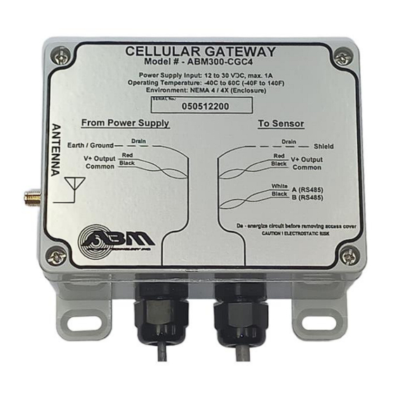
ABM300-CGC4
RS485 Cellular Gateway
Installation Manual
A – Introduction
This manual describes the requirements to successfully connect
up to eight ABM radar level sensor products in an RS485
network hosted by the ABM300 RS485 Cellular Gateway.
The Gateway not only acquires data from these sensors but can
also control them. Users have access to remotely change all alarm
related functions, while ABM experts can remotely recalibrate
and fine-tune the sensors for optimized performance in their
respective environments.
The Gateway can also be used to power any DC version ABM
radar level sensor (ABM300 series), which can simplify cable
routing in many cases.
B - Requirements
Cellular Network
The key to reliable Gateway operation is suitable cellular phone network access. While urban and developed areas
typically provide excellent cellular signal strength, there may be some installations where the cellular signal is weak. For
such locations, it is highly recommended that the installer determine an optimal mounting location by using a cell phone
display to assess the signal strength.
The standard antenna supplied with the Gateway has a magnetic-base and a 6' (2m) cable that allows mounting on top of
a tank or structure for optimal signal strength while mounting the Gateway in a more sheltered or accessible area. The
optional SMA-mounted antennas have slightly higher gain. For difficult installations, the ABM Sensor technical team can
provide advice regarding the use of directional antenna and extension cables.
Power Supply
The Gateway requires an input supply voltage of 12 to 30Vdc. Peak power is 6W (1A at 6V down to 0.2A at 30V). This
peak only occurs for a very short period during cellular transmissions.
If the Gateway is connected to supply DC-powered ABM sensors (see Appendix), it supplies an output of ≥18V, provided
the following requirements are met for the supply input voltage (V
•
For 1 to 3 sensors, V
•
For 4 sensors, V
•
For 5 sensors, V
•
For 6 to 8 sensors, V
The number and type of ABM sensors connected to the Gateway determine its total power requirement. Input current up to
600mA at 21-30Vdc may be required for an eight sensor configuration.
REV 0.0 April 18, 2023
≥ 12Vdc
IN
≥ 15Vdc
IN
≥ 18Vdc
IN
≥ 21Vdc
IN
730 The Kingsway Peterborough, ON K9J6W6 Canada
Tel: (705) 740 — 2010
Fax: (705) 740 — 2563
):
IN
Web: www.abmsensor.com
E-mail: info@abmsensor.com
Page 1
Advertisement

Related Manuals for ABM ABM300-CGC4

Summary of Contents for ABM ABM300-CGC4
- Page 1 ≥ 21Vdc For 6 to 8 sensors, V The number and type of ABM sensors connected to the Gateway determine its total power requirement. Input current up to 600mA at 21-30Vdc may be required for an eight sensor configuration. REV 0.0 April 18, 2023...
- Page 2 The Gateway is supplied with two 6ft (2m) #24AWG shielded twisted-pair pigtail cables – the minimum recommended wire size. ABM supplies all other sensor products with terminal blocks suitable for up to #14AWG wires. These terminals also accept two #18AWG conductors, which allows for direct wiring without junction boxes in some cases (see Section D Examples 1 and 4).
- Page 3 Terminal 4 connects internally to Terminal 7 (labelled “L2/N”). RS485 Network Initialization ABM sensors are supplied with a factory-default SID = 2, unless they were specifically ordered from ABM for a Gateway network configuration with a pre-assigned Serial ID (SID) sequence. The connection of more than one sensor having the same SID will result in communications failure.
- Page 4 D - Installation Examples 1. Single AC Powered Sensor The following example shows an AC powered sensor (ABM400 or ABM430 series), without a current output connection, connected to a Gateway. As the current loop output of the sensor is unused, the Gateway, located within 6ft (2m), is shown directly wired to the sensor through one cable gland, while the AC supply requires a second separate cable gland.
- Page 5 2. Single AC Powered Sensor with Current Output The following example is a variation of the first, but with the current output implemented. As the sensor is AC supplied, there is only one free cable gland for all low voltage wiring, so an external junction box is required to break out the current output.
- Page 6 3. Single DC Powered Sensor The following example is a variation of the previous two, except that the line-powered DC supply is remotely located and the Gateway does not supply the power to the sensor. The junction box is required, since there are conductors from three cables that need to be routed to the sensor. In this case, the Gateway supply output pair (red/black) is not connected.
- Page 7 4. Multiple DC Powered Sensors The following example shows the Gateway wired to control multiple sensors. As shown, the lower sensor is grounded through its metal housing, so the shield wire should not connect to either Terminals 3 or 6 in that sensor. However, the shield wire is connected to the upper (isolated) sensor. In multiple sensor configurations powered by the Gateway, the voltage of the power supply must be adequate to be able to meet the load requirements (see section “B –...
- Page 8 5. Multiple DC Powered Sensors The following example shows the Gateway wired to multiple sensors, each with a current loop output to the PLC. As they are all DC version sensors, they are powered directly from the 24Vdc supply. It is shown as a separate power supply, but one could use a 24Vdc supply from the PLC instead.
- Page 9 E - Appendix Following is a list of ABM sensors that are compatible for use with the Gateway. • DC Radar: ABM300-xxxYYC4 series: - may be indirectly earth-grounded through its mounting configuration (caution required re: shield wire) - may be powered from the Gateway sensor power output •...
Need help?
Do you have a question about the ABM300-CGC4 and is the answer not in the manual?
Questions and answers