
Subscribe to Our Youtube Channel
Summary of Contents for CAN DATAEAGLE 6000 Series
- Page 1 Manual DATAEAGLE 6000 Series - Wireless Schildknecht AG 26. Juli 2022 Schildknecht AG Haugweg 26 D-71711 Murr Tel.: +49 (7144) 89718 0 Mail: info@schildknecht.ag...
- Page 2 Manual DATAEAGLE 6000 Series - Wireless CAN...
- Page 3 DATAEAGLE Compact 6330 11145 DATAEAGLE X-treme 6330 11373 DATAEAGLE Compact 6340 11159 DATAEAGLE X-treme 6340 11375 Version Language Date 26. Juli 2022 Schildknecht AG Haugweg 26 D-71711 Murr Tel.: +49 (7144) 89718 0 Mail: info@schildknecht.ag Manual DATAEAGLE 6000 Series - Wireless CAN...
-
Page 4: Table Of Contents
6.1 Power supply connection ......33 6.2 CAN bus connection ......35 7 Commissioning Delivery state of the modules . - Page 5 Table of contents 7.2 Configuration CAN-Interface parameter ....38 7.2.1 ID Collection ....... 40 7.2.2 Whitelist .
-
Page 6: Introduction
It instructs not on the safe use of the machine in which the devices are or will be integrated. Information on this can be found in the operating instructions for the machine. Manual... -
Page 7: Trademark
1 Introduction 1.3 Trademark In this documentation the trademarks of the following companies and institutions are used: CAN CAN in AUTOMATION e.V. Manual DATAEAGLE 6000 Series - Wireless CAN... -
Page 8: For Your Safety
Use of the module • Observe all regulations on safety and accident prevention during project planning, installation, commissioning, operation and testing of the module. • When using aggressive medium, check the material resistance. Manual DATAEAGLE 6000 Series - Wireless CAN... -
Page 9: Intended Use
The DATAEAGLE transmits data in industrial applications. It is designed according to EN 60529 for protection class IP20 (Compact) or IP65 (X-treme) and can be used in control cabinets up to protection class IP67. The DATAEAGLE may only be used for the cases provided for in the operating instructions and manual and only in conjunction with the third-party devices and components recommended or approved by Schildknecht AG. -
Page 10: Environmentally Friendly Disposal
• Take the separated components to the appropriate recycling. Disposal The product can be returned to Schildknecht AG in case of disposal. This also applies to the original packaging and any batteries or rechargeable batteries. Devices contaminated with hazardous substances will not be taken back for repair or disposal. -
Page 11: Ce Declaration Of Conformity
2.5 Warranty and liability claims Warranty and liability claims are lost if • the product is not used as intended, • damage is due to failure to observe the operating instructions, • the staff was/is not knowledgeable. Manual DATAEAGLE 6000 Series - Wireless CAN... -
Page 12: Description
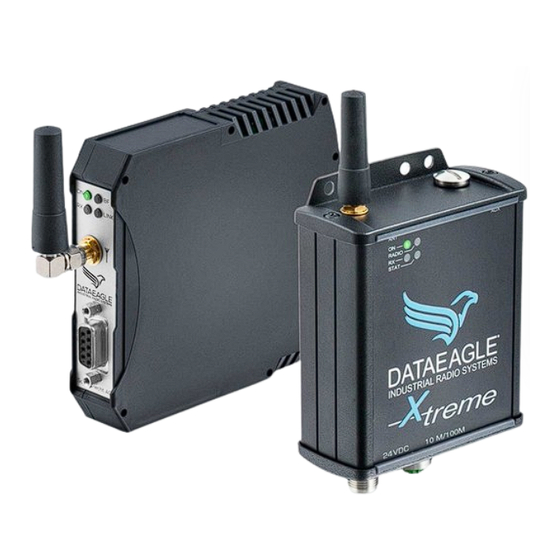
3 Description 3 Description 3.1 Introduction The modules of the DATAEAGLE 6000 series have been specially developed for the transparent transmission of CAN via radio. Different radio technologies, such as Bluetooth 2.4 GHz or 869 / 915 MHz in the licensed band, are used for transmission. CAN transmission speeds of up to 500 kbit/s can be configured using integrated data preprocessing. -
Page 13: Operating Principle Whitelist
Therefore, it is optionally possible to configure a whitelist using the DATAEAGLE Wizard configuration software. This is used to filter out the CAN telegrams that are to be transmitted by radio. The whitelist defines by means of the identifier which telegrams are to be transmitted by radio. -
Page 14: Dataeagle Compact
CAN Interface 9 pin SUB-D connector for CAN Pin assignment Description do not connect CAN_L do not connect do not connect do not connect do not connect CAN_H do not connect do not connect Manual DATAEAGLE 6000 Series - Wireless CAN... -
Page 15: Leds
Power not ok RX LED Indication State Description Yellow Flashing Radio reception No radio reception LINK LED Indication State Description LINK Blue On/Blinking Radio connection(s) active Radio Connection(s) inactive STAT LED - No function Manual DATAEAGLE 6000 Series - Wireless CAN... -
Page 16: Dataeagle X-Treme
3.4.1 Connections Power supply M12, A-coded, 5 pin (male) Description +24 VDC not connected not connected CAN Bus M12, A-coded, 5 pin (male), 5 pin (female) Description not connected not connected CAN_H CAN_L Manual DATAEAGLE 6000 Series - Wireless CAN... -
Page 17: Leds
Power not ok RX LED Indication State Description Yellow Flashing Radio reception No radio reception LINK LED Indication State Description LINK Blue On/Blinking Radio connection(s) active Radio Connection(s) inactive STAT LED - No function Manual DATAEAGLE 6000 Series - Wireless CAN... -
Page 18: Technical Data
Danger to life due to electric shock. Operation of the device only intended on 24 V DC (safety extra-low voltage). Death and serious injuries as well as considerable property damage can be the result. • The device may only be connected by an electrician in accordance with IEC 60364! •... -
Page 19: Dataeagle Compact 6710 - Article Number: 11166
100mW (EIRP) Indoor range 100m Outdoor range 300m Max. Number of radio slaves Antenna connection SMA Anschluss (female) - 50 Ohm Interface Max. CAN transmission rate 500 kBit/s CAN connection 9 pol. SUB-D Manual DATAEAGLE 6000 Series - Wireless CAN... -
Page 20: Dataeagle X-Treme 6710 - Article Number: 11361
Outdoor range 300m Max. Number of radio slaves Antenna connection SMA Anschluss (female) - 50 Ohm Interface Max. CAN transmission rate 500 kBit/s CAN connection M12, A-coded, 5 pin (male), 5 pin (female) Manual DATAEAGLE 6000 Series - Wireless CAN... -
Page 21: Dataeagle Compact 6730 - Article Number: 11268
Transmitting power 8dBm Indoor range 100m Outdoor range 300m Max. Number of radio slaves Antenna connection SMA Anschluss (female) - 50 Ohm Interface Max. CAN transmission rate 500 kBit/s CAN connection 9 pol. SUB-D Manual DATAEAGLE 6000 Series - Wireless CAN... -
Page 22: Dataeagle X-Treme 6730 - Article Number: 11278
Outdoor range 300m Max. Number of radio slaves Antenna connection SMA Anschluss (female) - 50 Ohm Interface Max. CAN transmission rate 500 kBit/s CAN connection M12, A-coded, 5 pin (male), 5 pin (female) Manual DATAEAGLE 6000 Series - Wireless CAN... -
Page 23: Dataeagle Compact 6330 - Article Number: 11145
869 MHz Transmitting power 500mW (EIRP) Indoor range 300m Outdoor range 1-3 km Antenna connection SMA Anschluss (female) - 50 Ohm Interface Max. CAN transmission rate 500 kBit/s CAN connection 9 pol. SUB-D Manual DATAEAGLE 6000 Series - Wireless CAN... -
Page 24: Dataeagle X-Treme 6330 - Article Number: 11373
500mW (EIRP) Indoor range 300m Outdoor range 1-3km Antenna connection SMA Anschluss (female) - 50 Ohm Interface Max. CAN transmission rate 500 kBit/s CAN connection M12, A-coded, 5 pin (male), 5 pin (female) Manual DATAEAGLE 6000 Series - Wireless CAN... -
Page 25: Dataeagle Compact 6340 - Article Number: 11159
915 MHz Transmitting power 500mW (EIRP) Indoor range 300m Outdoor range 1-3 km Antenna connection SMA Anschluss (female) - 50 Ohm Interface Max. CAN transmission rate 500 kBit/s CAN connection 9 pol. SUB-D Manual DATAEAGLE 6000 Series - Wireless CAN... -
Page 26: Dataeagle X-Treme 6340 - Article Number: 11375
500mW (EIRP) Indoor range 300m Outdoor range 1-3km Antenna connection SMA Anschluss (female) - 50 Ohm Interface Max. CAN transmission rate 500 kBit/s CAN connection M12, A-coded, 5 pin (male), 5 pin (female) Manual DATAEAGLE 6000 Series - Wireless CAN... -
Page 27: Mounting
• Suitable mounting location with regard to vibration and shock load, temperature and humidity (see ”4. Technical data” ) • Protected to prevent disconnection of the connecting cables by personnel or equipment. • Diagnostic LEDs of the device can be viewed during operation Manual DATAEAGLE 6000 Series - Wireless CAN... -
Page 28: Dimensions
5 Mounting 5.2 Dimensions DATAEAGLE Compact Dimensions in mm DATAEAGLE X-treme Dimensions in mm Manual DATAEAGLE 6000 Series - Wireless CAN... -
Page 29: Mounting The Components
→ Fasten the module at the designated place according to its fastening type. Mount: 1. Place the module from diagonally above onto the top-hat rail. 2. Press the module down firmly. The foot latch engages. The unit is firmly seated on the top-hat rail. Example: Manual DATAEAGLE 6000 Series - Wireless CAN... - Page 30 → Attach the module to the designated location according to its mounting method. Mount: 1. If necessary, drill holes for mounting according to the enclosed drilling template → https://www.schildknecht.ag/download/x-treme-drill-template- bohrschablone/. 2. Screw the device tightly. Manual DATAEAGLE 6000 Series - Wireless CAN...
-
Page 31: Mounting The Antennas
Tighten the screw connections of the antennas or antenna cables only hand- tight. FURTHER NOTES ON ANTENNA INSTALLATION! You will find further information on antenna mounting and alignment in our Antenna 101 → https://lp.schildknecht.ag/en/whitepaper-antenna101 Manual DATAEAGLE 6000 Series - Wireless CAN... -
Page 32: Disassembly And Module Replacement
2. Unscrew the antenna cable/antenna. Remove module (See assembly of the module) Mount new module (See assembly of the module) 1. Mount the new module. 2. Connect the wires to the new module (See Connection power supply). Manual DATAEAGLE 6000 Series - Wireless CAN... -
Page 33: Installation
Operation of the device only intended on 24V DC voltage (safety extra-low voltage) Death and serious injuries as well as considerable property damage can be the result. → Connection of the device may only be carried out by an electrician in accordance with IEC 60364! →... - Page 34 6 Installation Power supply - DATAEAGLE Compact Clamps Description 24 V DC Switching output Power supply - DATAEAGLE X-treme M12, A-coded, 5 pin (male) Description +24 VDC not connected not connected Manual DATAEAGLE 6000 Series - Wireless CAN...
-
Page 35: Can Bus Connection
CAN bus termination If the DATAEAGLE Compact is the fist or last participant on the physical CAN bus, the SUB-D socket of the connection cable must contain a terminating resistor (120 Ohm between CAN_L and CAN_H). Manual DATAEAGLE 6000 Series - Wireless CAN... - Page 36 CAN_H CAN_L CAN bus termination If the DATAEAGLE X-treme is the first or last station on the physical CAN bus, an M12 terminating resistor (e.g. article no.: 11888) must be screwed onto one of the two M12 connections. Manual...
-
Page 37: Commissioning
7 Commissioning WARNING! Risk of burns Loosening or making electrical connections during operation is prohibited! In case of non-observance, there is a risk of electric arcs which can lead to burns. → Disconnect the module from the power supply. CAUTION! -
Page 38: Configuration Can-Interface Parameter
Wizard configuration software. Select Autodetect COM Port and then Connect to connect to DATAEAGLE and read the configuration. The DATAEAGLE must be switched on for this. Select in the menu tree: Interface → CAN Parameter Manual DATAEAGLE 6000 Series - Wireless CAN... - Page 39 IDs that are to be transmitted on radio transmission via radio. (See 7.2.2 Whitelist) from local cross traffic Service ID CAN Message ID for diagnosis CAN Message ID and control of the DATAEAGLE. (See 7.2.3 Service ID) Manual DATAEAGLE 6000 Series - Wireless CAN...
-
Page 40: Id Collection
Collection”. If the ”ID Collection” option is not selected in the configuration, DATAEAGLE operates in the ”ID Transparent” mode. In the operating mode ”ID Transparent” all CAN IDs received on the cable side are collected and transmitted via radio. Example: The ”Controller”... - Page 41 7 Commissioning In the operating mode ”ID Collection” all CAN IDs received on the cable side are collected and identical IDs are overwritten until the next radio transmission. Example: The ”Controller” sends CAN messages for the station „CAN Drive“ (ID:181 + ID:182 + ID:281 - multiple).
-
Page 42: Whitelist
7 Commissioning 7.2.2 Whitelist Message IDs can be added to the whitelist that are to be transmitted via radio. Message IDs that are not entered are ignored. The message ID is entered and added in hexadecimal form. It is possible to configure individual CAN message IDs (select ”Whitelist index”) or to specify a range (select ”Whitelist range”). -
Page 43: Service Id (Currently Only For 2.4 Ghz Bluetooth)
7 Commissioning 7.2.3 Service ID (Currently only for 2.4 GHz Bluetooth) The service ID can be used to control the radio links, set the whitelist and read diagnostic data. The response message is sent with the service ID +1. The message ID is entered and added in hexadecimal form. - Page 44 7 Commissioning Structure of the CAN messages via the service ID: Command Function CAN Payload example Byte 1 - Byte 8 Byte 1 (dez) → Request - Service ID ← Response - Service ID + 1 Request diagnostic →0,0,0,0,0,0,0,0 data radioretries ←0,0x01,0x01,0x01,0x01,0,0,0...
- Page 45 7 Commissioning Command Function CAN Payload example Byte 1 - Byte 8 Byte 1 → Request - Service ID ← Response - Service ID + 1 Whitelist Range 1 → 200,0,0,0,0x01,0x02,0x03,0x04 Start ID (4 Byte) ←200,0,0,0,0x01,0x02,0x03,0x04 Whitelist Range 1 →...
-
Page 46: Diagnosis Via Terminal Mode
7 Commissioning 7.2.4 Diagnosis via terminal mode CAN diagnostics is possible via the terminal function of DATAEAGLE Wizard. The following steps are necessary for this. In the DATAEAGLE Wizard, use the ”Tools” menu to select ”Terminalmode”. A new window opens. Check the COM port and select ”Connect”. - Page 47 6 … 500 kBaud CAN Error State 0 … No Errors 0x01 … Stufferror 0x02 … Formerror 0x04 … ACK Error CAN RX Error Counter according ISO11898-1 CAN TX ERROR Counter according ISO11898-1 Manual DATAEAGLE 6000 Series - Wireless CAN...
-
Page 48: Configuration Radio Parameters
Connect DATAEAGLE to the PC via the USB cable and start the DATAEAGLE Wizard configuration software. Select Connect to connect to DATAEAGLE and read the configuration. The DATAEAGLE must be switched on for this. Select in the menu tree: Interface → Radio Manual DATAEAGLE 6000 Series - Wireless CAN... - Page 49 Master has the station address 01 and the partner addresses 02 and 03. Slave 1 has the station address 02 and the partner address 01. Slave 2 has the station address 03 and the partner address 01. Manual DATAEAGLE 6000 Series - Wireless CAN...
-
Page 50: Ghz Bluetooth - Dataeagle Compact/X-Treme 6710
NOTE If a radio system was ordered as a set (set configuration), no change is necessary here. The Bluetooth MAC address must be read out at the master and entered at the slave. Manual DATAEAGLE 6000 Series - Wireless CAN... -
Page 51: 2,4 Ghz Bluetooth 5 - Dataeagle Compact/X-Treme 6730
The Bluetooth MAC address must be read out at the slave and entered at the master. If a radio network is configured, several Bluetooth MAC addresses must be configured in the master (BLE slave MAC 1, BLE slave MAC 2, ...). Manual DATAEAGLE 6000 Series - Wireless CAN... -
Page 52: 869 Mhz - Dataeagle Compact/X-Treme 6330
7.3.3 869 MHz - DATAEAGLE Compact/X-treme 6330 NOTE If a radio system was ordered as a set (set configuration), no change is necessary here. Select in the menu tree: Interface → Radio → 869 MHz Manual DATAEAGLE 6000 Series - Wireless CAN... - Page 53 However, it should be noted that at high RF rate only 1 system is possible due to the available bandwidth! It makes sense to reduce the transmitting power in order not to influence neighboring radio systems in the same frequency band! Manual DATAEAGLE 6000 Series - Wireless CAN...
-
Page 54: 915 Mhz - Dataeagle Compact/Xtreme 6340
7.3.4 915 MHz - DATAEAGLE Compact/Xtreme 6340 NOTE If a radio system was ordered as a set (set configuration), no change is necessary here. Select in the menu tree: Interface → Radio → 900 MHz Manual DATAEAGLE 6000 Series - Wireless CAN... - Page 55 DATAEAGLE radio systems in parallel operation are to be operated with different radio channels! It makes sense to reduce the transmitting power in order not to influence neighboring radio systems in the same frequency band! Manual DATAEAGLE 6000 Series - Wireless CAN...
-
Page 56: Tips And Tricks
→ Always use shielded cables for interfaces and power supplies. → Use shielding braid with a density of at least 85 %. → Always connect the shield on both sides to the EMC ground (usually PE). Bus and power lines Manual DATAEAGLE 6000 Series - Wireless CAN... - Page 57 Electronic or electrical components without a closed metal housing are a source of interference for RF fields. → Make sure that all electronic or electrical components that could be a source of interference from RF fields have a closed metal housing. Manual DATAEAGLE 6000 Series - Wireless CAN...
-
Page 58: Optimal Antenna Mounting
→ Route protective conductors of the individual system components in a star configuration to the equipotential bonding rail. 8.2 Optimal antenna mounting Instructions for antenna mounting and alignment can be found in our Antenna 1x1 → https://www.schildknecht.ag/download/antennen-1mal1/ Manual... -
Page 59: Legal Notice
The reason for this is that we have no influence on the changes or uses of the technical documentation and even minor changes to the initial product or deviations from the intended uses can render the specifications recorded in the technical documentation incorrect. For this reason, the customer is also obliged... - Page 60 Schildknecht AG have been integrated into the advertised products of the customer.The customer shall, when using trademarks of Schildknecht AG, indicate in a suitable manner that these are trademarks of Schildknecht AG. Manual DATAEAGLE 6000 Series - Wireless CAN...
Need help?
Do you have a question about the DATAEAGLE 6000 Series and is the answer not in the manual?
Questions and answers