Table of Contents
Advertisement
Quick Links
INSTALLATION AND OPERATION
MANUAL
E–4 ALARM
ANNUNCIATOR
for Raytherm H, WH, & P
Models 514-4001
IMPORTANT SAFETY INSTRUCTIONS. READ AND FOLLOW ALL
INSTRUCTION. SAVE THESE INSTRUCTIONS.
NOTE: The instructions in this manual are for the use of qualified individuals specially trained and experienced
in the installation and maintenance of this type of equipment and related system components. Installation and
service personnel are required by some states to be licensed. Persons not qualified shall not attempt to install,
service, or maintain this equipment.
This manual should be maintained in legible condition and kept adjacent to the unit or in a safe place for future
use.
Effective: 03-25-22
Replaces: 04-09-08
P/N 240691 Rev. 4
Advertisement
Table of Contents

Summary of Contents for Rheem Raypak E-4
- Page 1 INSTALLATION AND OPERATION MANUAL E–4 ALARM ANNUNCIATOR for Raytherm H, WH, & P Models 514-4001 IMPORTANT SAFETY INSTRUCTIONS. READ AND FOLLOW ALL INSTRUCTION. SAVE THESE INSTRUCTIONS. NOTE: The instructions in this manual are for the use of qualified individuals specially trained and experienced in the installation and maintenance of this type of equipment and related system components.
- Page 2 Revision 4 reflects the following changes: General document reorganization in conjunction with a reformat using InDesign. Edits for clarity made throughout in text, tables and figures along with incorporation of additional metric measurement references. Configuration section added on page 4. Updated Figure 4 with drawing 901094.03 Rev.
-
Page 3: Table Of Contents
TABLE OF CONTENTS 1. WARNINGS ............4 Check Your Power Source ........6 Pay Attention to these Terms ........4 Wiring Power to the E–4 Alarm ....... 6 Power Test .............. 6 2. CONFIGURATIONS AVAILABLE: ......4 E–4 Alarm Indicator Lights ........6 3. -
Page 4: Warnings
1. WARNINGS Pay Attention to these Terms Indicates the presence of immediate hazards which will cause severe personal injury, death or substantial DANGER property damage if ignored. ndicates the presence of hazards or unsafe practices which could cause severe personal injury, death or WARNING substantial property damage if ignored. -
Page 5: Receiving Equipment
3. RECEIVING EQUIPMENT Remote Alarm Panel (E-6 Option) Thank you for selecting the Raypak E-4 Alarm. It is our The Remote Alarm Panel (sales order option E-6) provides sincere hope that you will enjoy its outstanding design and a mounting panel and the necessary electrical components ease of use. -
Page 6: Electrical Installation
Mount the E–4 Alarm using the mounting bracket and Wiring Power to the E–4 Alarm appropriate 3/8" or 1/4" diameter hardware in four (4) places. • Observe Polarity A minimum of 18 inches (45.7 cm) clearance from the • Observe proper wire colors while making electrical front, and 6 inches (15.2 cm) clearance on all other sides connections. -
Page 7: Field Wiring Connection Points
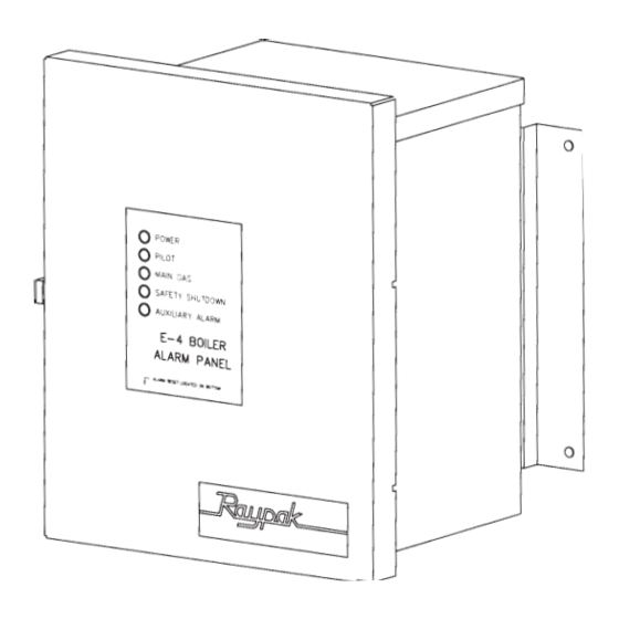
Standard Indicator Lights: Օ (Green) Indicates that 120 VAC is being supplied to the E–4 Alarm Board. Power Օ (Amber) Indicates that the pilot valve circuit has been energized. Pilot Օ (Green) Indicates that the main gas valve has been energized. Main Gas (Red) Indicates that a safety shutdown has occurred. -
Page 8: Remote Alarm Wiring Diagram
7. REMOTE ALARM PANEL WIRING DIAGRAM D (24V RETURN) A (MV) C (PV) B (MV/PV) E (FAULT) T R M P N... -
Page 9: Installation Verification
8. INSTALLATION VERIFICATION PROCEDURE Register • Before proceeding any further, please verify that the user registration form has been completed and mailed. Mechanical Installation • Verify that the mechanical installation has been completed in accordance with the instructions. System Module Installation •... -
Page 10: Illustrated Parts List
9. ILLUSTRATED PARTS LIST E-6 OPTION E-7 OPTION c t i " 3 l l e " 4 l l e Remote Alarm & Reset Switch Kit 005632... -
Page 11: Warranty
10. WARRANTY LIMITED WARRANTY E-4 & Accessories SCOPE OF WARRANTY : Raypak, Inc. ("Raypak") warrants to the original owner the Control System to be free from defects in materials and workmanship under normal use and service for the applicable warranty period. In accordance with the terms of this Limited Warranty, RAYPAK will furnish a replacement or repair, at our option, any defective part which fails in normal use and service during the applicable warranty period. - Page 12 NOTES Raypak, Inc., 2151 Eastman Avenue, Oxnard, CA 93030 (805) 278-5300 www.raypak.com...
Need help?
Do you have a question about the Raypak E-4 and is the answer not in the manual?
Questions and answers