Sign In
Upload
Download
Table of Contents
Contents
Add to my manuals
Delete from my manuals
Share
URL of this page:
HTML Link:
Bookmark this page
Add
Manual will be automatically added to "My Manuals"
Print this page
×
Bookmark added
×
Added to my manuals
Manuals
Brands
Airfi Manuals
Fan
60
Installation and operating instructions manual
Airfi 60 Installation And Operating Instructions Manual
Hide thumbs
1
2
Table Of Contents
3
4
5
6
7
8
9
10
11
12
13
14
15
16
17
18
19
20
21
22
23
24
25
26
27
28
page
of
28
Go
/
28
Contents
Table of Contents
Bookmarks
Table of Contents
Table of Contents
Warnings and Cautions
General Information
General Information in Brief
Basic Operation of the Air Handling Unit
Controls
Fans
Heat Recovery Cell
Protective Functions
Installation
Installation of Ventilation Ducts
Wall Installation
Ceiling Installation 1
Floor Mounting Set
Vapour Barrier Sealing Plate
Condensate Removal
Airfi Water Seal
Kitchen Bypass
Electricity, Control Cables and Controllers
Duct Radiators
Controllers
Uno
Sento
Mille-Wire
Mille-Wifi
Airfi App
Airfi Cloud
Seven Segment
Bus Control
Exhaust Hood Controls
Commissioning
Air Flow Rates
Basic Air Flow Control
Maintenance
Opening
Filters
Heat Recovery Cell
Fans
Cleaning the Duct System
Condensation Water
Airfi Water Seal
Other Maintenance
Technical Specifications
Dimensional Drawings
Air Flow
Potentiometric Setup - Seven-Segment
Other Functions
Advertisement
Quick Links
Download this manual
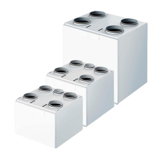
Model 60
Model 100
Model 130
Model 150
the Airfi App
Download
to your smart device.
You get an easy-to-use weekly clock
and many other functions.
www.airfi.fi/app
INSTALLATION AND OPERATING INSTRUCTIONS
MORE THAN PURE AIR
Table of
Contents
Previous
Page
Next
Page
1
2
3
4
5
Advertisement
Table of Contents
Need help?
Do you have a question about the 60 and is the answer not in the manual?
Ask a question
Questions and answers
Related Manuals for Airfi 60
Fan Airfi 100 Installation And Operating Instructions Manual
(28 pages)
Fan Airfi 130 Installation And Operating Instructions Manual
(28 pages)
Fan Airfi 150 Installation And Operating Instructions Manual
(28 pages)
This manual is also suitable for:
100
130
150
Table of Contents
Print
Rename the bookmark
Delete bookmark?
Delete from my manuals?
Login
Sign In
OR
Sign in with Facebook
Sign in with Google
Upload manual
Upload from disk
Upload from URL


Need help?
Do you have a question about the 60 and is the answer not in the manual?
Questions and answers