Table of Contents
Advertisement
Quick Links
Advertisement
Table of Contents

Related Manuals for KATEK ghost ONE


Summary of Contents for KATEK ghost ONE
- Page 1 ONE Operating Instructions - English...
- Page 2 Copyright and trademarks Copyright 2023 eSystems MTG GmbH All rights reserved. Subject to availability and technical modifications. All hardware and software names used are trade names and/or registered tra- demarks of the relevant companies. Issued by: 02/2023...
-
Page 3: Table Of Contents
Contents 1 Introduction 1.1 Intended use 1.2 Documentation concept and target group 1.3 Copyright 1.4 Legal notices 1.5 Means of representation 2 Safety 2.1 Safety symbols 2.2 Intended use 2.3 Safety information for operation 3 Product overview 3.1 Design 3.2 Functions 3.3 Items supplied 3.4 Access data 3.5 Web app / mobile app for Wallbox... - Page 4 Contents 7 Operation 7.1 Login/logout 7.2 Information in the overview 7.3 Charging a vehicle 7.3.1 Starting charging 7.3.2 Charging with RFID chip 7.3.3 Pausing charging 7.3.4 Finishing charging 7.3.5 Configuring the PLC connection to the vehicle 7.3.6 Charging information and settings 7.4 Enabling / disabling free charging (charging without authentication) 7.5 Managing the approved list 7.5.1 Adding an RFID chip to the approved list...
- Page 5 Contents 8.2 Cleaning the Wallbox 9 Troubleshooting 9.1 Performing a self-test 9.2 Fixing errors 9.2.1 Error list 9.2.2 Identifying and fixing errors 9.2.3 Error codes 9.3 Initiating emergency measures 10 Shutdown and uninstalling 11 Storage 12 Disposal 13 Technical data 14 Technical glossary 15 Index...
-
Page 6: Introduction
1 Introduction Introduction Intended use The Wallbox ghost ONE is a Wallbox with network capability. It is used for charging electric vehicles that comply with the generally applicable standards and directives for electric vehicles. It is suitable for stationary use indoors and outdoors and in private and semi-... -
Page 7: Copyright
1 Introduction Type of Contents Target group instructions Assembly and Describe the mechanical and Electrical engineers and spe- installation electrical installation of the cialist companies approved instructions Wallbox. Work steps described by the network operator in these instructions must only who are responsible for be performed by qualified spe- installation and com-... -
Page 8: Means Of Representation
1 Introduction any manipulation to the wiring or the built-in energy meter can be detected. The manufacturer’s seal must not be removed or damaged during the service life of the Wallbox. Damage to the official calibration conformity seal or damage to or removal of the operator seal results in immediate revocation of the official calibration conformity of the Wallbox, regardless of the intervals for official calibration tests. -
Page 9: Safety
2 Safety Safety Safety symbols In these instructions, warning notices appear before sequences of actions that involve a risk of injury or damage. The measures described to prevent the hazard must be adhered to. Layout of warning notices SIGNAL WORD Cause of the hazard Remedy Action 1... -
Page 10: Intended Use
Useful tips and recommendations, as well as information on efficient and fault-free operation. Intended use The Wallbox ghost ONE is a Wallbox with network capability. It is used for charging electric vehicles that comply with the generally applicable standards and directives for electric vehicles. - Page 11 2 Safety Store the operating instructions in a location that is easily accessible to the operator/user. Only use the designated accessories. Observe the ambient and storage conditions, see Technical data on page 76. Do not stick anything onto the Wallbox or block it with objects. Do not remove, manipulate or bypass the manufacturer’s seal or lock.
-
Page 12: Product Overview
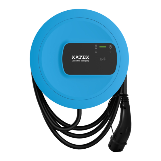
3 Product overview Product overview Design The Wallbox ghost ONE has the following design: Fig. 1: Design (ghost ONE Basic and ghost ONE MID versions) Housing Decorative cover Front panel Vehicle cable Energy meter (ghost ONE MID version only) -
Page 13: Functions
Front panel Energy meter Note For information about the front panel, see Front panel on page 19. Functions The AC Wallbox ghost ONE has network capability and provides the following functions: Function Description Intelligent charging Smart charging using ISO 15118 functions... - Page 14 3 Product overview Function Description Remote control inter- Web app faces Backend server via OCPP 1.6 Backend server via OCPP 2.0.1 (with future soft- ware update) Authentication and aut- Plug & charge horisation Auto charge Free charging RFID Web app Remote via OCPP Connectivity Ethernet...
- Page 15 3 Product overview Rating plate Fig. 3: Rating plate (example) Manufacturer Model name Serial number Date of manufacture Hardware status Software version Power and nominal current Mains voltage Mains frequency Integrated residual current operated protective device Foreign body protection (IP protection type) Ambient temperature Disposal information, see also Disposal on page 75...
-
Page 16: Items Supplied
More screws may be supplied than are necessary. Component Quantity Wallbox (consisting of housing, cover, decorative cover) Vehicle cable “Type 2 (not with ghost ONE ERK version) Assembly and installation instructions Quick start guide Access data letter Declaration of conformity... -
Page 17: Access Data
Personal unblocking key if the password is no longer known. External metering For the ghost ONE ERK version only, for electronic device public key verification of billing data received. QR code For access to the Wallbox via the web app or mobile app. -
Page 18: Web App / Mobile App For Wallbox
3 Product overview Note Always store the access data letter or any access data changed at a later date in a secure location. When delivered, the Wallbox has individual access data such as pass- words, which means that subsequent changes are not essential. Web app / mobile app for Wallbox The web app / mobile app has the following design: Fig. -
Page 19: Front Panel
Front panel The following illustration provides an overview of the displays and controls on the front panel: Fig. 5: Front panel overview (left: ghost ONE Basic and ghost ONE MID; right: ghost ONE ERK) Network connection LED Brightness sensor Charge level LED... -
Page 20: Displays And Controls
4 Front panel Displays and controls LEDs The following LEDs are provided on the front panel, see also Front panel on page 19. They indicate the following information: Type of information Colour Meaning Charge level White, continuous No vehicle connected or the vehicle has not yet been detected. - Page 21 4 Front panel Type of information Colour Meaning Operating / error con- For further detailed infor- dition mation, see Error list on page 48. White The Wallbox is ready for operation. White, flashing Software update is availa- ble. White, pulsing Software update in pro- gress.
- Page 22 RFID chip Socket Note The socket is only available on the ghost ONE ERK Wallbox version. The front panel has a type 2 socket in accordance with IEC 62196. The socket can be locked and unlocked, see Locking/unlocking the socket.
- Page 23 4 Front panel Only use the appropriate connector: Supply type Standard EN 62196-2 Design Type 2 Connector type Connector and socket Voltage range ≤ 480 V RMS Identification...
-
Page 24: Assembly And Installation
5 Assembly and installation Assembly and installation Further information For detailed information about assembly and installation of the Wallbox, refer to the Assembly and installation instructions. -
Page 25: Commissioning
6 Commissioning Commissioning Connecting the wallbox 6.1.1 Connecting via Ethernet Note To configure the Ethernet connection for the Wallbox, you must be logged in as a service user. Prerequisite To connect the Wallbox via Ethernet, an Ethernet cable must be installed. See Assembly and installation instructions. -
Page 26: Connecting Via Wifi Hotspot
6 Commissioning No connection to web browser established using Ethernet cable If a connection could not be established, check the following: 1. Check whether the Wallbox is connected to a network switch or an appro- priately configured computer and that it is active and is not showing any errors. -
Page 27: Authentication On The Wallbox
6 Commissioning Note The Wallbox is fitted with an internal firewall and security mechanisms for IP- based network communication. Only install the Wallbox in private networks and use a firewall. Use either WPA2 (default setting) or WPA3 for a secure WiFi connection. Operation in WiFi mode is not possible with protocols that are unencrypted or do not meet the latest security standards, for example WEP. - Page 28 6 Commissioning Note Ensure that the access data is spelt completely correctly, paying par- ticular attention to capitalisation. After five incorrect password entries, there is a delay before you can make another attempt. 3. The first time you log in as a standard user, read and accept the disclai- mer and the information on protection of personal data.
-
Page 29: Operation
7 Operation Operation Login/logout Note In everyday operation, use the standard user role wherever possible to pre- vent system settings from being accidentally changed. Logging in using the web app / mobile app In the login screen, on the Standard tab for a standard user or the Tech- nician tab for the service user, enter the personal password from the access data letter or the password you have set yourself and confirm. -
Page 30: Charging A Vehicle
A graphical representation of the energy consumption in kWh can be seen for the charging in progress. Charging a vehicle 7.3.1 Starting charging 1. For ghost ONE ERK version only: Plug the vehicle cable into the socket on the Wallbox. - Page 31 7 Operation Note The connector may be automatically locked when a vehicle connection is detected, see Locking/unlocking the socket. 2. Plug in the vehicle cable on the vehicle. The Wallbox creates a charging approval and starts charging in one of the ways described below: Note If OCPP is enabled and a connection to the OCPP backend server has been esta-...
-
Page 32: Charging With Rfid Chip
7 Operation Authorisation Description Prerequisites Auto charge Vehicles with advan- Vehicle supports advanced com- ced communication munication and it is enabled on in accordance with the vehicle. ISO 15118 can PLC vehicle connection is enabled authenticate them- for the Wallbox. selves on the Wall- Vehicle has been registered on the box using the vehicle Wallbox with its vehicle address. -
Page 33: Pausing Charging
7 Operation DANGER Risk of injury due to RFID sensor for persons with cardiac pacemaker or defibrillator If you use a cardiac pacemaker, maintain a distance of at least 60 cm from the RFID sensor on the front panel. If you use a defibrillator, maintain a distance of at least 40 cm from the RFID sensor on the front panel. -
Page 34: Configuring The Plc Connection To The Vehicle
Information in the overview page 29. Disconnect the vehicle cable on the vehicle. For ghost ONE Basic and ghost ONE MID versions only: Securely store the vehicle cable on the Wallbox. For ghost ONE ERK version only: Unplug the vehicle cable from the socket on the Wallbox and store securely. -
Page 35: Enabling / Disabling Free Charging (Charging Without Authentication)
7 Operation 2. On the Charging current screen, configure the value for the Maximum charging current (A). The maximum value that can be set is automatically limited by the current- carrying capacity of the vehicle and the mains connection. The current-carrying capacity of the mains connection is configured during installation of the Wallbox, see Assembly and installation instructions. -
Page 36: Changing The Rfid Chip Name In The Approved List
7 Operation 3. Hold up the RFID chip to the RFID sensor on the front panel of the Wall- box and select Read RFID chip. As soon as the RFID chip has been detected, the identification of the RFID chip (UUID) is displayed in the Set up RFID chip screen. In addition, an acoustic response tone sounds and the RFID sensor LED briefly lights up green. -
Page 37: Removing An Rfid Chip From The Approved List
Managing smart charging / smart home 7.6.1 Configuring the Wallbox for a smart home EMS via EEBUS Note The Wallbox ghost ONE supports home energy management systems (HEMS) that are EEBUS-compatible. Showing EEBUS-compatible devices / HEMS Select the Connections, EEBUS-HEMS option in the navigation. -
Page 38: Configuring General Settings
7 Operation Connecting an HEMS Note To pair an HEMS with the Wallbox, you must be logged in as a service user. 1. Select the Connections, EEBUS-HEMS option in the navigation. 2. On the EEBUS-HEMS screen, under EEBUS devices found select the right arrow for the HEMS you want to connect. -
Page 39: Showing System Settings
7 Operation 7.7.2 Showing system settings 1. Select the Wallbox settings, System information option in the navi- gation. The following types of system settings are displayed on the System infor- mation screen: Network information Electronic rating plate Licenses: License information for software components used in the web app. -
Page 40: Setting Units
7 Operation 7.7.3 Setting units 1. Select the Wallbox settings, Units option in the navigation. The Units screen is opened. 2. Select the relevant unit, e.g. temperature. 7.7.4 Enabling/disabling the earth monitoring system Note To enable/disable the earth monitoring system, you must be logged in as a service user. -
Page 41: Updating The Software
7 Operation Updating the software 7.9.1 Software update information Display on the front panel Note These displays are only visible if there are no active errors in the Wallbox. If the error LED is flashing white, a software update is available. If the error LED is pulsing white, the software is currently being updated. -
Page 42: Manually Updating The Software
7 Operation Date of the last software update, including version number Status: Software for update downloaded, Software update in pro- gress, Software update complete, Software update failed Information on whether a new software update is available Version information of the last software update for each of the fol- lowing software types: Bundle version, COM software version, PWR software version Displaying the change log... -
Page 43: Performing A Local Software Update
7 Operation A corresponding message is displayed in the Overview in the web app / mobile app. Restrictions on control of automatic software updates If there is active OCPP communication, the software update is performed exclusively via the backend server. 7.9.4 Performing a local software update In addition to server-based software updates, a local software update is also possible. - Page 44 7 Operation The operator provides the EVSE ID. 5. Select Connect. Connection started is displayed as the status. The connection is established and the Disconnect option is available. 6. Enable/configure the following optional settings: Allow charging to start remotely: Remote authorisation of char- ging, e.g.
-
Page 45: Service And Cleaning
8 Service and cleaning Service and cleaning Performing recurring checks WARNING Risk of injury due to inadequately qualified personnel. This can cause serious injuries and damage to equipment. Only trained and appropriately qualified personnel are to work on the Wall- box. - Page 46 DIN VDE 0100 in Germany). Preparing for checks under official calibration law Note This information is only relevant for the Wallbox ghost ONE ERK version. Cleaning the Wallbox for official calibration. Contact and make arrangements with a provider of checks under official...
-
Page 47: Cleaning The Wallbox
8 Service and cleaning Cleaning the Wallbox DANGER Risk of death due to electric shock or fire Water in the Wallbox can lead to life-threatening injuries due to electric shock and fire. Never immerse the Wallbox or connectors in water. Do not direct any water jets, e.g. -
Page 48: Troubleshooting
9 Troubleshooting Troubleshooting Performing a self-test The Wallbox performs an automatic self-test of its components each time it is started. In addition, the internal residual current operated protective device is tested before every charging cycle. If an error has been detected in the self-test, it is entered in the error list, see Error list on page 48. -
Page 49: Identifying And Fixing Errors
9 Troubleshooting If there are multiple errors, the error LED lights up in the colour assigned to the highest error category. Error status The following error statuses are defined: Error sta- Meaning Active The error is active and the cause of the error has not yet been fixed. -
Page 50: Error Codes
9 Troubleshooting Note on critical and non-critical errors Once the cause of the error has been fixed, the status of the error immediately changes to Passive. 4. If multiple errors are displayed, fix the errors in order of priority, starting with fatal errors, followed by critical errors and so on. - Page 51 9 Troubleshooting Error Category Type of error Measures to fix error code 0x100003 Fatal Power controller Press the button on the front power supply panel for at least 8 seconds to self-test error restart the Wallbox. If the error is still displayed after repeated restarts, contact support.
- Page 52 9 Troubleshooting Error Category Type of error Measures to fix error code 0x100025 Non-critical Temperature Press the button on the front compensation panel for at least 8 seconds to for LEDS failed. restart the Wallbox. Continued operation of the Wallbox is pos- sible but the colours of the LEDs may not match those described in these instructions.
- Page 53 9 Troubleshooting Error Category Type of error Measures to fix error code 0x100101 Fatal Fault current During charging, fault currents (DC) detected can occur. The Wallbox detects these and then switches off as a precaution. This can be caused by unwanted side-effects of the domestic installation.
- Page 54 9 Troubleshooting Error Category Type of error Measures to fix error code 0x100104 Fatal Earth moni- Check the domestic installation toring system to ensure the Wallbox is correctly indicating earthed, if necessary with the errors. assistance of a qualified electrical engineer.
- Page 55 9 Troubleshooting Error Category Type of error Measures to fix error code 0x100121 Fatal Vehicle connec- Press the button on the front tor socket self- panel for at least 8 seconds to test failed restart the Wallbox. If the error is still displayed after repeated restarts, contact support.
- Page 56 9 Troubleshooting Error Category Type of error Measures to fix error code 0x300005 Non-critical PLC connection Check that the on-board charger to vehicle com- on your electric vehicle is func- munication tioning correctly. If you have error connected your own vehicle cable to the socket, check it and if necessary use a different vehicle cable.
- Page 57 9 Troubleshooting Error Category Type of error Measures to fix error code 0x300101 Non-critical Ethernet Check the cable, switch, network connection configuration and security set- error tings on the connected com- puter. The wallbox is not suitable for direct connection to another computer (ad-hoc connection).
- Page 58 9 Troubleshooting Error Category Type of error Measures to fix error code 0x300300 Non-critical RFID module Press the button on the front faulty panel for at least 8 seconds to restart the Wallbox. If the error is still displayed after repeated restarts, charging approval is only possible using one of the other authorisation options or by...
- Page 59 9 Troubleshooting Error Category Type of error Measures to fix error code 0x300401 Fatal Connection to Press the button on the front energy meter panel for at least 8 seconds to interrupted restart the Wallbox. If the error is still displayed after repeated restarts, you must have the installation of the energy meter checked by a qualified electrical...
- Page 60 9 Troubleshooting Error Category Type of error Measures to fix error code 0x401013 Non-critical Plug & charge Check the vehicle cable and the (PnC): Invalid PnC configuration on the vehicle. payment Charging without PnC is possible method as an alternative. 0x401014 Non-critical Plug &...
- Page 61 9 Troubleshooting Error Category Type of error Measures to fix error code 0x40101B Non-critical Plug & charge Check the vehicle cable and the (PnC): Incor- PnC configuration on the vehicle. rect energy Charging without PnC is possible transmission as an alternative. mode 0x40101C Non-critical Plug &...
- Page 62 9 Troubleshooting Error Category Type of error Measures to fix error code 0x401024 Non-critical Plug & charge Press the button on the front (PnC): Internal panel for at least 8 seconds to software error restart the Wallbox. If the error (PLC connec- is still displayed after repeated tion)
- Page 63 9 Troubleshooting Error Category Type of error Measures to fix error code 0x40102A Non-critical Energy mana- Check the configuration of your gement sys- energy management system in tem: Service for terms of the tariff settings. cost-optimised charging is not available. 0x402000 Critical OCPP con-...
- Page 64 9 Troubleshooting Error Category Type of error Measures to fix error code 0x500000 Non-critical Light sensor fai- Press the button on the front panel for at least 8 seconds to restart the Wallbox. If the error is still displayed after the restart, operation of the device can con- tinue anyway.
- Page 65 9 Troubleshooting Error Category Type of error Measures to fix error code 0xD1210A Critical Internal com- Press the button on the front munication panel for at least 8 seconds to error on the restart the Wallbox. If the error comm con- is still displayed after repeated troller restarts, contact support.
- Page 66 9 Troubleshooting Error Category Type of error Measures to fix error code 0xE10213 Non-critical Undervoltage Have the installation checked by on phase L2 a qualified electrical engineer. In particular, the mains connection has to be checked and if necessary repaired (high voltage resistance measurement, visual inspection for kinks, crushing etc.).
- Page 67 9 Troubleshooting Error Category Type of error Measures to fix error code 0xE10241 Critical Input current Have the installation checked by on phase L2 too a qualified electrical engineer. In high particular, the mains connection has to be checked and if necessary repaired (high voltage resistance measurement, visual inspection for kinks, crushing...
- Page 68 9 Troubleshooting Error Category Type of error Measures to fix error code 0xFF000D Fatal Invalid enco- The vehicle cable is faulty or can- ding value for not be operated with this vehicle char- Wallbox. If you are using your ging cable cur- own vehicle cable, try using a dif- rent-carrying ferent vehicle cable.
- Page 69 9 Troubleshooting Error Category Type of error Measures to fix error code 0xFF0104 Critical No charging pos- Wait until the Wallbox has cooled sible due to cri- back down to the permitted ope- tical rating temperature. For indoor temperature installation, check the air con- (sensor on ditioning system / room cooling power con-...
- Page 70 9 Troubleshooting Error Category Type of error Measures to fix error code 0xFF0302 Non-critical Charging cur- Allow for a longer charging time. rent reduction For indoor installation, check the due to high tem- air conditioning system / room perature (sen- cooling settings.
- Page 71 9 Troubleshooting Error Category Type of error Measures to fix error code 0xFF0404 Critical No charging pos- Wait until the Wallbox has cooled sible due to cri- back down to the permitted ope- tical rating temperature. For indoor temperature installation, check the air con- (sensor in out- ditioning system / room cooling put path)
-
Page 72: Initiating Emergency Measures
9 Troubleshooting Error Category Type of error Measures to fix error code 0xFF0909 Non-critical Temperature Press the button on the front sensor on LED panel for at least 8 seconds to outside valid restart the Wallbox. If the error range is still displayed after the restart, operation of the Wallbox can con- tinue anyway. -
Page 73: Shutdown And Uninstalling
10 Shutdown and uninstalling 10 Shutdown and uninstalling Further information For detailed information about shutting down and uninstalling the Wallbox, refer to the Shutdown and uninstalling instructions. -
Page 74: Storage
11 Storage 11 Storage Clean the Wallbox before storage, see Cleaning the Wallbox on page 47. Store the Wallbox in the original packaging or other suitable packaging in a clean and dry location. Observe the permissible storage temperature. For detailed information about the permissible storage temperature and other environmental specifications, see Technical data on page 76. -
Page 75: Disposal
12 Disposal 12 Disposal The Wallbox is subject to the EU Directive 2012/19/EU on waste electrical and electronic equipment. Disposal of the wallbox Prerequisite Before disposal, a qualified electrical engineer must disconnect the Wall- box from the power supply and shut it down in accordance with the regulations, see Assembly and installation instructions, “Shutdown and uninstalling”. -
Page 76: Technical Data
13 Technical data 13 Technical data Electrical data ghost ONE ver- Basic sion GHO11- GHO22- GHO11- GHO22- GHO22- E10K E10K E21K E21K E22K Power [kW] Mains voltage 220 - 240 / 400 Mains frequency 50 / 60 [Hz] Rated current... - Page 77 13 Technical data ghost ONE ver- Basic sion GHO11- GHO22- GHO11- GHO22- GHO22- E10K E10K E21K E21K E22K Rated current of switchgear com- bination [A] Rated con- ditional short-cir- cuit current Icc [kA] Rated load fac- tor RDF Mains type TT/TN 3 and 1-phase;...
- Page 78 13 Technical data ghost ONE ver- Basic sion GHO11- GHO22- GHO11- GHO22- GHO22- E10K E10K E21K E21K E22K Supply line, clam- Rigid: 0.5 - 16 ping range [mm Tightening torque 1.5 - 1.8 [Nm] Ethernet RJ45 Cat. 5/6/7 External control...
- Page 79 13 Technical data Ambient and storage conditions ghost ONE ver- Basic sion GHO11- GHO22- GHO11- GHO22- GHO22- E10K E10K E21K E21K E22K Protection rating IP55 Shock resistance IK10 Degree of con- tamination Positioning Open air or inside building Stationary / mobile...
-
Page 80: Technical Glossary
Technical glossary 14 Technical glossary Alternating Current Direct Current EEBUS Communication interface for energy management in the IoT (Internet of Things) HEMS Home Energy Management System ICCID Integrated Circuit Card IDentifier. Identifies the SIM card required for LTE. IMEI International Mobile Equipment Identity. Identifies the transmission and receiving module required for LTE. - Page 81 Technical glossary MODBUS/RTU MODBUS/Remote Terminal Unit Communication between energy meter and wallbox connected via RS485 OCPP Open Charge Point Protocol Over The Air Personal Unblocking Key Photovoltaics (technology for converting solar energy into electrical energy) RFID Radio Frequency Identification. Contactless identification of people and objects using radio waves SELV Safety Extra Low Voltage...
-
Page 82: Index
Index Copyright 7 15 Index Data 7 Design 12 Access data 17 Mobile app 18 Ambient conditions 79 Web app 18 Approved list Disclaimer 7 Add RFID chip 35 Displays 19 Edit RFID chip data 36 Displays and controls 20 Remove RFID chip 37 Disposal 75 Assembly 24... - Page 83 Index Free charging Disable 35 OCPP Enable 35 Connect wallbox 43 Front panel 19 Official calibration conformity 7 Button 22 Official calibration law Displays and controls 20 Recurring check 46 Overview 19 Operator seal 8 RFID sensor 22 Overview Functions 13 Information 29 HEMS Pause...
- Page 84 Index RFID sensor 22 Wallbox Cleaning 47 Safety 9 Design 12 Safety information 10 Warning notices Safety symbols 9 Layout 9 Screenshots 8 Symbols 9 Self-test 48 Web app Set units 40 Design 18 Setting the earth monitoring Login 29 system 40 Logout 29 Shutdown 73...
- Page 85 Support Hotline: +49 7024 40 59 88 00 E-Mail: support@esystems-mtg.de Product Security Incident Response Team psirt@esystems-mtg.de eSystems MTG GmbH Bahnhofstr. 100 73240 Wendlingen www.esystems-mtg.de...
Need help?
Do you have a question about the ghost ONE and is the answer not in the manual?
Questions and answers