Table of Contents
Advertisement
Quick Links
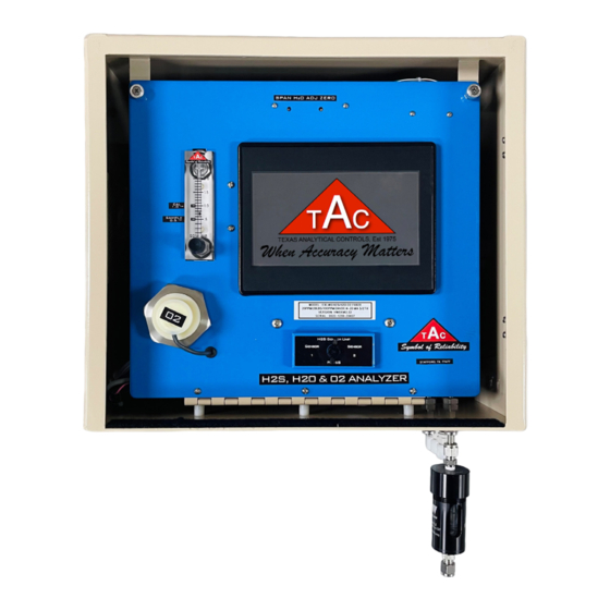
Hydrogen Sulfide, Water, Oxygen & Carbon Dioxide Analyzer
TAC-H
S/H
O/O
2
2
Analyzer Instruction Manual
2
Table of Contents
2.1
2.2
2.3
2.4
2.5
2.5.1
2.6
PART 3
3.1
3.2
PART 4
OPERATION
4.1
4.2
4.3
4.3.1
H
S Calibration Menu
2
4.3.2
2
4.4
2
4.5
2
4.6
4.6.1
H
S Sensor Saturation Alarm
2
4.6.2
4.7
4.8
4.8.1
4.8.2
4.9
4.10
4.11
4.12
5.1
5.2
2
5.3
2
5.4
2
5.5
5.6
6.1
6.2
TEXAS ANALYTICAL CONTROLS
4418 Bluebonnet Drive | Stafford, TX 77477
(281) 240-4160
www.tac-controls.com
Advertisement
Table of Contents

Summary of Contents for TAC H2S/H2O/O2
-
Page 1: Table Of Contents
Hydrogen Sulfide, Water, Oxygen & Carbon Dioxide Analyzer TAC-H Analyzer Instruction Manual Table of Contents PART 1 DEFINITIONS PART 2 INSTALLATION Safety Requirements Mounting the Instrument Sample Conditioning System Electrical Connections Communication Outputs 2.5.1 Optional Isolated 4-20 mA Tubing Connections & Instructions PART 3 START-UP &... -
Page 2: Part 1 Definitions
For proper function, apply a constant pressure of approximately 10 psig. Sample pressure may require multiple pressure drops. You can purchase a sample-conditioning system from TAC. NOTE: Sample plate must be mounted below the analyzer to keep liquids from reaching the analyzer. -
Page 3: Sample Conditioning System
2 Installation TAC-H Pg. 3 Sample Conditioning System The sample-conditioning system ensures a clean, regulated sample for the analyzer. Sample-gas composition and pressure, along with other factors, may require modifying the conditioning system for a specific application. Mount the sample-conditioning system below the analyzer if possible. The typical system may consist of a sample probe, drip pot, one or two regulators, and a membrane filter. -
Page 4: Electrical Connections
2 Installation TAC-H Pg. 4 2.4 Electrical Connections The input power and the 4-20mA connections are in the analyzer’s enclosure. The power switch is in the upper left-hand corner of the enclosure. Use it to recycle the power as needed. -
Page 5: Tubing Connections & Instructions
2 Installation TAC-H Pg. 5 Tubing Connections & Instructions STANDARD SAMPLE The sample flows into the analyzer through the SAMPLE IN inlet and sweeps out of the instrument through the SAMPLE VENT SAMPLE outlet. The calibration and nitrogen standards are connected to VENT the analyzer through the STANDARD IN inlet. -
Page 6: Start-Up & Operation Overview
Depending on when your analyzer was purchased some of the features illustrated in our manuals may or may not be included. For an updated program call TAC at 281-240-4160. The analyzer uses a 7-inch touchscreen programmable logic controller (PLC), with a removable microSD card that data logs and stores the TAC program. -
Page 7: Typical Flow Diagrams
3 Start-up & Operation Overview TAC-H Pg. 7 Typical Flow Diagrams Typical H S Flow Diagram NOTE: Cal Valve not required when analyzer has a Manual Cal Valve. Typical H O Flow Diagram Typical O Flow Diagram TEXAS ANALYTICAL CONTROLS 4418 Bluebonnet Drive | Stafford, TX 77477 | (281) 240-4160 | www.tac-controls.com... -
Page 8: Screen Display
Pg. 8 Screen Display After the analyzer is powered up, it displays warm-up screens, then the TAC address and phone number, then the main screen. On subsequent screens, press the READINGS button at any time to return to the main screen. -
Page 9: Calibration And Start-Up Of The Analyzer
The H S portion of the analyzer does not require calibration • To return to the main screen, at start-up because it is calibrated at the factory. TAC press READINGS. recommends calibration two weeks after gas is flowing. • To return to the menu screen, Calibration of the H S portion is recommended monthly. -
Page 10: Calibrate Menu
4 Controls and Their Operation TAC-H Pg. 10 The O readings will begin to decrease. When they drop below 100 ppm, the analyzer no longer is over range. Once the readings stabilize, calibrate the analyzer with O calibration gas. (With a bottle of 25 ppm, the target counts should be approximately 8,000.) -
Page 11: O 2 Calibration
4 Controls and Their Operation TAC-H Pg. 11 To Calibrate H S continued 7 Turn ON the calibration gas and adjust the flow meter to 1.0 SCFH. 8 Press YES to confirm. The display will flash “Calibration in progress.” Each H S sensor is calibrated twice. - Page 12 4 Controls and Their Operation TAC-H Pg. 12 To Calibrate O continued 7 Turn manual valve to STANDARD IN. Confirm that the flow-meter ball drops to zero. Turn on the calibration gas and adjust the flow meter between 0.5 and 1.0.
-
Page 13: H 2 S Sensor Settings Menu
S Sensor-setting button enables you to turn on or off one of the H S sensors, as well as adjust the sample and clearing times. Do not change Clearing Time/ Sample Time, etc., without consulting TAC tech support. If either H S sensor is too weak to operate properly it can be turned off. -
Page 14: Alarm Settings Menu
4 Controls and Their Operation TAC-H Pg. 14 BUMP TEST IN PROGRESS MENU READINGS PSIG FRONT VIEW MENU READINGS Sample In PSIG + / - + / - + / - + / - Standard In Alarm Settings Menu To Change the Alarm Settings... - Page 15 4 Controls and Their Operation TAC-H Pg. 15 4.6.1 H S Sensor Saturation Alarm The default for sensor saturation is “latch.” Sensor saturation means the H S levels exceed the analyzer’s range. If the sensors are in saturation mode, the analyzer remains in clearing mode. The sample bypasses the sensors until the operator presses the ACKNOWLEDGED button to clear the latch.
-
Page 16: Pump & Flow Fail Alarms
4 Controls and Their Operation TAC-H Pg. 16 4.6.2 Pump & Flow Fail Alarms There are two pressure sensors in each analyzer; one for the internal pump and one if the flow is obstructed to the analyzer. The internal pump that clears the H S sensors between cycles typically lasts 3-5 years. -
Page 17: Analog-Out Settings Menu
4 Controls and Their Operation TAC-H Pg. 17 Analog-Out Settings Menu To Change Analog-Out Settings From the menu screen, press the ANALOG OUT SETTINGS button. 2 The analog output settings menu will be displayed. Pressing the desired buttons allows you to set/change the 4-20 mA. -
Page 18: Rtu/Modbus Menu
4 Controls and Their Operation TAC-H Pg. 18 4.8 RTU/Modbus Menu To Change the RTU/Modbus Settings From the menu screen, press the RTU MODBUS button. 2 Turn MODBUS OFF when configuring settings. Press the desired button(s) to set/change the modbus settings. -
Page 19: Tcip/Ip Menu
4 Controls and Their Operation TAC-H Pg. 19 4.8.2 TCIP/IP Menu To Change the TCIP Settings From the menu screen, press the TCIP MODBUS button. 2 Press the desired button(s) to set/change the settings. 3 Use the UP/DOWN ARROWS or keypad to enter the required data and press ENTER to save. -
Page 20: Oem Settings Menu
TAC-H Pg. 20 4.10 OEM Settings Menu Approval by TAC tech support is required to enter this screen. To Change the OEM Settings From the menu screen, press the OEM SETTINGS button. 2 Enter the password and follow the steps. -
Page 21: Password Protection Feature
From the menu screen, press the USER PASSWORD button. 2 Press PASSWORD ENABLED or DISABLED to set. The Password is set to 2030. To change the default password consult the TAC Support team. TEXAS ANALYTICAL CONTROLS 4418 Bluebonnet Drive | Stafford, TX 77477 | (281) 240-4160 |... -
Page 22: Part 5 Maintenance
• The instrument’s accuracy depends on keeping vent lines perfectly clear, and bug screens on the vents help with this. You may purchase additional bug screens from TAC. Replacing H S Sensors Replace both sensors at the same time. Allow them to warm up for 10 minutes, then calibrate. - Page 23 5 Maintenance TAC-H Pg. 23 Replacing H O Sensor Extremely FRAGILE Extremely connection FRAGILE Step 1: Disconnect flow tubing (x2) Step 2: Disconnect Heater Wire Pig Tail connection at orange connecters. at orange socket (x1) nsor Assembly ation Added) O Sensor Assembly Installed...
-
Page 24: Replacing H 2 O Sensor
5 Maintenance TAC-H Pg. 24 O2 Sensor Replacement Replacing O Sensor Unscrew Nut Replacing Membrane Filter Texas Analytical Controls To keep a clean sample to the analyzer, it is important to replace the membrane filter as needed. O2 Sensor Replacement... -
Page 25: Analyzer Enclosure Dimensions
5 Maintenance TAC-H Pg. 25 Analyzer Enclosure Dimensions 9" 15" " " " 9" " TEXAS ANALYTICAL CONTROLS 4418 Bluebonnet Drive | Stafford, TX 77477 | (281) 240-4160 | www.tac-controls.com... -
Page 26: Part 6 Troubleshooting
Pg. 26 Frozen Screen – Run/Idle Mode If the PLC freezes or gets stuck on the TAC Logo screen it maybe in the Idle mode. To Change to Run Mode Press the right corner of the touch screen to bring up the System Menu 2 Press the SYSTEM button. -
Page 27: Plc Loses Program - Reload Program
6 Troubleshooting TAC-H Pg. 27 PLC Loses Program — Reload Program If the PLC loses the program, it can be reloaded. To Reload Program 4 Press LOAD CLONE. 5 Press OK. Press the right corner of the touch screen to bring up the System Menu 6 Enter password 5625 and press ENTER. - Page 28 TAC-H Pg. 28 Thank you for purchasing one of our analyzers. Since 1975, TAC has been supplying analyzers to the oil field industry. We have always had three main objectives: • To provide instruments of the highest quality • To continue to improve our systems and add features and capabilities •...
Need help?
Do you have a question about the H2S/H2O/O2 and is the answer not in the manual?
Questions and answers