
Subscribe to Our Youtube Channel
Summary of Contents for Engcon MIG2 CAN
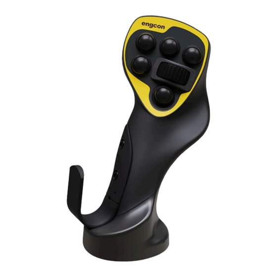
- Page 1 Installation instructions MIG2 CAN engcon for Doosan | 8001850, MIG2-299-MAP51-CAN-4R-13B-1NO-Doosan Article 9000674 | Version 1.2 Installation instructions in English...
- Page 2 Dear Customer, Thank you for choosing a product from engcon. engcon is the market leader in tiltrotators and tools for excavators. We represent innovation, knowledge and experience, and we develop our products with a focus on the customer's needs. Please visit our website for contact information and details about the rest of our product range.
-
Page 3: Table Of Contents
4.3.6. Attachment kit..................16 4.3.7. Bellows washer standard.................16 4.4. Overview, MIG2 CAN..................17 4.4.1. Install the break-out cable 8001833............18 4.5. Connect MIG2 CAN to cable 8001833............18 4.6. Connect MIG2 CAN to the machine..............19 4.7. Decals......................20 4.7.1. Build your MIG2 decal................20 4.7.2. - Page 4 Table of Contents 7.3. 8002010......................29...
-
Page 5: Introduction
- Packaging to be sorted at source and recycled for materials. - Paper to be sorted at source and recycled for materials. If in doubt, contact the environmental manager at engcon. 1.3. Technical support and spare parts Contact information for support and spare parts can be found at www.engcon.com. -
Page 6: Product Approval
1.4. Product approval 1.4.1. Declaration of incorporation of partly completed machinery Product: engcon DC3 controlsystem Manufacturer: engcon Nordic AB - Industricentragatan 4, 833 93 Strömsund, Sweden THE OBJECTS DESCRIBED ABOVE IS IN CONFORMITY WITH Applied and fulfilled essential requirements of 2006/42/EC. -
Page 7: Eu Declaration Of Conformity
The declaration concerns the control system fitted to the excavator and not any interchangeable equipment that may be installed to the excavator, such as a engcon tiltrotator. The object has radio connection features for setting and calibration purposes. -
Page 8: Safety
2 Safety 2. Safety REMARKS The stated safety information is independent of the base machine and is directly concerned with the engcon DC2. REMARKS Other safety instructions can be found in the tiltrotator user manual. 2.1. General It is important that you read and understand all the warning texts before you begin installing or using the product and any accessories supplied. -
Page 9: Delivery Contents
3. Delivery contents 3.1. 8001850 MIG2-299-MAP51-CAN-4R-13B-1NO-Doosan Part number Designation Quantity 8001313 GripMIG2-L-258-CAN-2R-7NO/NC-Doosan 8001314 GripMIG2-R-259-CAN-2R-1NO-6NO/NC-Doosan 8001833 Cable Breakout MIG2 CAN - Doosan 841161 Decal - Symbol sheet - MIG2 841868 Decal - MIG2 Empty 841869 Decal - MIG2 9000674 Installation instructions-MIG2 CAN-DC3-Doosan-8001850... -
Page 10: Installation
WARNING If you have any doubts concerning the safety aspects of your knowledge, the equipment or work, contact a dealer or engcon Nordic AB. Incorrect installation affect safety. WARNING Switch off power when working on the electrical system and remove any live objects before starting work Risk of personal injury. -
Page 11: Remove The Original Joystick
4 Installation 4.2. Remove the original joystick 4.2.1. Measure the height of the original joystick By measuring the height of the original grip you will know how high the MIG2 grips must be when they are installed later. 4.2.2. Remove the original joystick Remove the original grip including cabling. -
Page 12: Installing The Mig2 Can
4 Installation 4.3. Installing the MIG2 CAN 4.3.1. Fitting the attachment bolt and lock nut Fit the lock nut from the original joystick and attachment bolts in the control valve where the original joystick was previously installed. REMARKS It may be necessary to cut the attachment bolt to a suitable length before installing as illustrated below. -
Page 13: Cable Routing
4 Installation 4.3.2. Cable routing Wrap the cable one turn around the attachment bolt. 4.3.3. Attachment point 1. Undo the lock bolt located beneath the grip to expose the ball joint. 2. 5. Install the attachment bolt in the ball joint located in the grip. 3. -
Page 14: Reinstallation
4 Installation 4.3.4. Reinstallation Position Description Secure the cables to the attachment bolts using cable ties to minimise wear. Continue running the cabling without exposing it to the risk of pinching or other damage. -
Page 15: Cover Plate, Hand Rest
4 Installation 4.3.5. Cover plate, hand rest Position Part number Description 841865 Hand rest, left 841892 Cover plate, hand rest, left 841893 Cover plate, hand rest, right 841866 Hand rest, right... -
Page 16: Attachment Kit
4 Installation 4.3.6. Attachment kit Position Part number Description 8000196 Attachment kit, MIG2, left 8000195 Attachment kit, MIG2, right 4.3.7. Bellows washer standard Position Part number Description 1033831 Bellows washer... -
Page 17: Overview, Mig2 Can
4 Installation 4.4. Overview, MIG2 CAN Position Part number Description 8001313 Left MIG2 grip M12, 5-pin, A-coded male Deutsch, 2-pin female 8001314 Right MIG2 Grip... -
Page 18: Install The Break-Out Cable 8001833
2. Connect the break-out cable between the disconnected connectors. Position Description TILT ROTATOR CABIN 2 Cable Breakout MIG2 CAN - Doosan 4.5. Connect MIG2 CAN to cable 8001833 Position Description Cable Breakout MIG2 CAN - Doosan M12 kabel från MIG2-handtag... -
Page 19: Connect Mig2 Can To The Machine
4 Installation Position Description MIG2 grip 4.6. Connect MIG2 CAN to the machine Position Description Deutsch connector from the machine’s joystick cabling. Deutsch connector from the MIG2 joystick MIG2 grip... -
Page 20: Decals
4 Installation 4.7. Decals WARNING Replace damaged or illegible signs and decals before using the machine. Risk of personal injury and damage to property. WARNING Check that the function decals correspond to the machine functions before starting work. Risk of personal injury. -
Page 21: Apply Decals
Affix the MIG2 decals supplied in a conspicuous place in the operator's cab, without obscuring operator visibility. 4.7.3. Cut away misleading information on the original decals REMARKS Machine functions that still apply must not be cut away. REMARKS The engcon decals do not completely replace the machine’s original decals. -
Page 22: On Completion
Risk of personal injury. IMPORTANT Do not attempt to use or maintain engcon's products before you have read and understood all of the information about them and the base machine. Pay particular attention to the safety information. -
Page 23: Documenting The Installation
5 On completion 5.2. Documenting the installation Fill in the machine card or similar to document the installation. Note which instruction books (with the version numbers) were used for the installation and complete any checklist. This information is important for repairs, service or any warranty claims on the machine, and must be kept available for presentation in the event of market checks. -
Page 24: Glossary
6 Glossary 6. Glossary 6.1. Abbreviations Term Description Base Control Module CAN to CAN Digging Control 3 engcon (Engström Construction) engcon Machine Link engcon Positioning System engcon TechTool Master Gateway Module MIG2 Microprop Grip 2 Q-Safe Light Module Quick hitch Panel Module... -
Page 25: Drawings And Schematics
7 Drawings and schematics 7. Drawings and schematics 7.1. 8001359... - Page 26 7 Drawings and schematics...
- Page 27 7 Drawings and schematics 7.2. 8001833...
- Page 28 7 Drawings and schematics...
- Page 29 7 Drawings and schematics 7.3. 8002010...
- Page 30 7 Drawings and schematics...
- Page 31 Notes ..................................................................................................................................................................................................................................................................................................................................................................................................................................................................................................................................................................................................................................................
- Page 32 International Box 111, SE-833 21 Strömsund, Sweden +46 (0) 670-178 00, international@engcon.com www.engcon.com...
Need help?
Do you have a question about the MIG2 CAN and is the answer not in the manual?
Questions and answers