Table of Contents
Advertisement
Advertisement
Table of Contents

Related Manuals for curt DISCOVERY 51126


Summary of Contents for curt DISCOVERY 51126
- Page 1 INSTALLATION MANUAL 51126 DISCOVERY NEXT BRAKE CONTROLLER ™...
-
Page 2: Table Of Contents
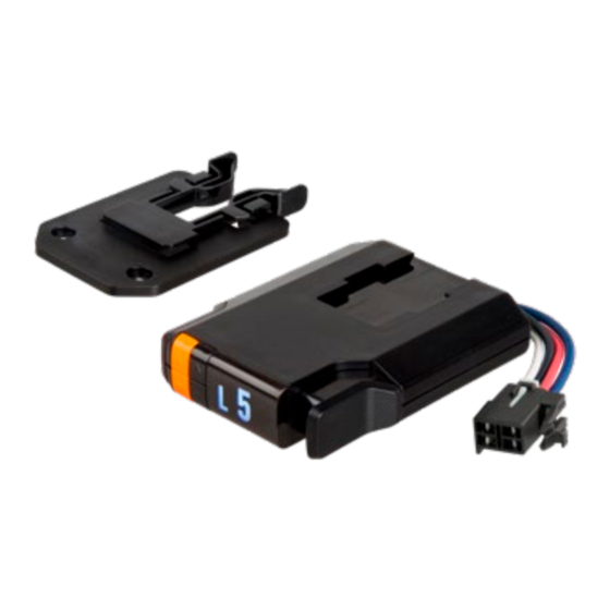
TABLE OF CONTENTS CONTROLS & COMPONENTS TOOLS LIST Controls & Components page 2 1. Main module with CURT quickplug 1. Drill 2. Mounting Bracket 2. Drill bit, 1/8" Tools List page 2 3. Mounting Screws 3. Phillips screwdriver Before You Begin page 3 4. -
Page 3: Before You Begin
(ITBC) integrated trailer brake control, see the • Brake control harness, supplied with the tow vehicle (if equipped) vehicle owners manual for any necessary instructions for install. • CURT quick plug harness - custom connector for specific vehicles (see the CURT catalog for availability) CONTROLS •... -
Page 4: Wiring The Controller
If the mating plug supplied with the may void warranty. Check owners manual for harness information. vehicle is no longer available, a CURT quick plug can be used. See the 2. Locate the vehicle plug and remove any anti-rattle foam. Remove CURT catalog for application information. -
Page 5: Wiring Diagram
WIRING DIAGRAM CURTMFG.COM PAGE 5 51126-INS-RA PRODUCT SUPPORT: 877.287.8634 • • •... -
Page 6: Mounting The Brake Controller
MOUNTING THE BRAKE CONTROLLER 1. Mount the unit securely to a solid surface where it is easily accessible to the driver. The area behind the mounting location must be clear to prevent damage to vehicle if using screws. The angle at which it's mounted will not effect the operation or calibration of this controller (Fig 1). -
Page 7: Modes & Indicators On The Led Display
MODES & INDICATORS ON THE LED DISPLAY The LED display shows the output setting when the control is activated. It is used to set up and monitor the brake controller and can be used when troubleshooting. There are six modes of operation and eight indicator sequences (shown below). - Page 8 Some tow vehicle circuits do not allow power for brake lights • Press the orange mode button (#3) to scroll through from a second source. In these applications, the CURT custom wiring controller options until you reach day / night mode.
- Page 9 GAIN CONTROL (LEFT SIDE OF DISPLAY - FARTHEST LEFT) AUTO (SHOWS OUTPUT FROM CONTROL TO TRAILER BRAKES) The gain control establishes the maximum amount of power • Shows output power from 0.5 to 9.9 when available to the trailer brakes when braking. The only exception the vehicles brakes are being applied would be when the manual control is set up for 100% braking.
- Page 10 OVERLOAD INDICATORS START UP INDICATOR • Indicates when the brake controller is in • Indicates when the brake controller an overload or short-circuit condition is in start up mode or restart mode. • The screen shows brake overload or short condition •...
-
Page 11: Initial Setup
DISCONNECTED INDICATOR INITIAL SETUP Once all electrical connections are complete inside the vehicle, plug the • Indicates when the trailer has been disconnected trailer electrical connector into the tow vehicle plug. The brake controller (flashing) or if the brakes are pressed with no trailer will sense the trailer upon connecting to the trailer after 10-15 seconds. -
Page 12: Test Drive & Adjustment
3. Alligator clip test leads OR wire and wire nuts into sleep mode (blank / black screen). Beginning with the gain adjustment, 4. CURT #51515 / #51516 quick plug with pigtails OR push pins locate a vacant street or parking area and drive forward on a dry and level paved or concrete surface. - Page 13 IMPORTANT: Read and follow all ™ to the bulb. Once the CURT start up screen disappears or turns warnings and cautions shown on the battery. black, the control module is ready. Pressing the manual control...
-
Page 14: Troubleshooting Guide
TROUBLESHOOTING GUIDE - NO TRAILER CONNECTED Condition Display Problem Cause Possible Solution Display does not light up when brake No power to controller, no ground, Check and repair connections pedal or manual control is used reveresed black and white wires (see 'Wiring' section) or circut breaker blown Display shows 'Not Connected'... - Page 15 TROUBLESHOOTING GUIDE - WITH TRAILER CONNECTED Condition Display Problem Cause Possible Solution Display shows 'not connected' when power is No connection between brake controller Confirm connection to trailer connected applied to controller. No trailer brakes when and trailer brakes – blue wire circuit Confirm connector terminal positions brake pedal or manual control is used Check trailer...
- Page 16 WARRANTY & PRODUCT REGISTRATION CURT stands behind our products with industry-leading warranties. To get copies of the product warranties, register your purchase or provide feedback, visit: curtmfg.com/registration Connect with us...
Need help?
Do you have a question about the DISCOVERY 51126 and is the answer not in the manual?
Questions and answers
what makes the brakes on the micro mini winnebago rv smoke when brakes are applied?