Table of Contents
Advertisement
Advertisement
Table of Contents

Related Manuals for Shortridge Instruments AIRDATA ADM-850L


Summary of Contents for Shortridge Instruments AIRDATA ADM-850L
- Page 1 AIRDATA MULTIMETER ADM-850L ™ ELECTRONIC MICROMANOMETER • AIR FLOW • VELOCITY • PRESSURE • TEMPERATURE• OPERATING INSTRUCTIONS Shortridge Instruments, Inc. 7855 East Redfield Road / Scottsdale, Arizona 85260-3430 Phone (480) 991-6744 • Fax (480) 443-1267 ® www.shortridge.com ADM-850L 07/29/09...
-
Page 2: Table Of Contents
CONTENTS 1.0 INTRODUCTION 2.0 SPECIFICATIONS 3.0 EXTERNAL FEATURES 3.1 KEYPAD 3.2 FEATURES ON SIDES AND BACK OF METER 4.0 DISPLAY MESSAGES AND PROMPTS 4.1 READ PROMPTS 4.2 MEASUREMENT READOUTS 4.3 FUNCTION READOUTS 5.0 USING THE AIRDATA MULTIMETER 5.1 GENERAL USE 5.2 TREND READINGS 6.0 VELOCITY MEASUREMENT 6.1 PITOT TUBE VELOCITY MEASUREMENT... - Page 3 REPLACEMENT PARTS LIST INDEX Copyright © Shortridge Instruments, Inc., 2009. All rights reserved. This information may not be reproduced or duplicated in any manner, or for any purpose, without permission in writing from Shortridge Instruments, Inc. Addendums or revisions made to this manual after July 2009 may be found at www.shortridge.com.
- Page 4 ILLUSTRATIONS 3.1 ADM-850L METER FRONT AND BACK 6.1 PITOT TUBE 7.1 STATIC PRESSURE PROBE 8.1 ADT442 TEMPROBE 8.2 AIRDATA MULTITEMP 10.1 FRAME STORAGE 10.2 FLOWHOOD IN CASE 10.3 FLOWHOOD ASSEMBLY 10.4 2X2 FRAME ASSEMBLY 10.5 1X4 FRAME ASSEMBLY 10.6 2X4 FRAME ASSEMBLY 10.7 1X5 FRAME ASSEMBLY 10.8 3X3 FRAME ASSEMBLY ADM-850L 07/29/09...
-
Page 5: Introduction
1.0 INTRODUCTION 1.1 GENERAL DISCUSSION These instructions will be much easier to follow if the meter is in front of you as you read through them. You can note the various connections and press the keys, observing the displayed results as you read through the various procedures. The operation of the meter is quite simple and straightforward, as will become apparent after a little practice. -
Page 6: Specifications
AIR FLOW: Measured in cubic feet per minute (cfm) or liters per second (L/s), corrected for local air density. This function requires the use of the Shortridge Instruments' Series 8400 Backpressure Compensating FlowHood System. The measurement range is 25 to 2500 cfm supply and 25 to 1500 cfm exhaust. Accuracy is ± 3% of reading ± 7 cfm from 100 to 2000 cfm (nonbackpressure compensated readings). - Page 7 The approximate level of charge remaining in the batteries is displayed using a schematic battery symbol in the third or fourth character of most displays. The battery symbol will have four different appearances, representing the progressive decrease in the level of charge as the meter is used. A solid battery symbol represents a fully charged battery.
-
Page 8: External Features
3.0 EXTERNAL FEATURES 3.1 KEYPAD Control Name Function ON/OFF Turns the meter on or off. MODE Sequential action for all measurement modes (air flow, pitot tube velocity, differential and absolute pressure, temperature). UNITS Alternate action for English or metric units. READ Initiate measurement;... -
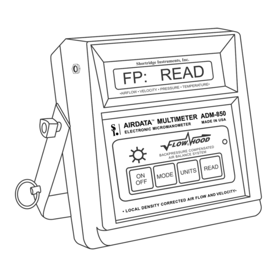
Page 9: Adm-850L Meter Front And Back
External Read Jack for 10 Digit, 0.4" LCD Display Pushbutton Handle Plug Light On/Off Battery Charger Jack MODE Flow/DiffPres/Temp/Pitot/AbsPres GRN LED Indicates if charger is plugged in UNITS English/Metric READ Read/Halt Trend Readings Power On/Off Pushbutton Reset Switch Positive (+) Pressure Port Negative (-) Pressure Port Flaps Jack for FlowHood Flaps Plug Threaded Insert for Attachment to FlowHood... -
Page 10: Display Messages And Prompts
4.0 DISPLAY MESSAGES AND PROMPTS 4.1 READ PROMPTS The following ten prompts all include the term READ, which is a signal for the operator to press the READ key to trigger the actual measurement. The units designation will always be followed by either a symbol for the level of battery charge, the light symbol or the TREND mode symbol. -
Page 11: Function Readouts
Metric Units Bar n.nnn Indicates that the result represents an absolute pressure measurement (bar). (One bar = 100 kPa). C ± nnn.n Indicates that the displayed result represents a temperature measurement ( LS c ± nnnn Indicates that the result represents an air flow measurement (L/s). "c" indicates that the result has been compensated for backpressure effects. - Page 12 changes may be made during the AUTO ZERO period. The meter will also perform a brief self-calibration cycle periodically throughout normal operation. BATTERY This message may be displayed as part of a longer message sequence such as NO LIGHT/BATTERY/TOO LOW. CF CORR This message indicates that the air flow measurement being performed is in cfm and will be backpressure compensated.
- Page 13 NO FLAPS This message advises that the flaps plug on the FlowHood has not been connected to the meter for air flow measurements. The meter senses the position of the flaps through the flaps plug. NO LIGHT This message will appear as part of the NO LIGHT/BATTERY/TOO LOW sequence, when the battery charge is too low to support use of the backlight.
- Page 14 TOO HOT or TOO COLD If the internal temperature of the meter exceeds its operational limits, the meter will display TOO HOT or TOO COLD and shut down. The meter must be cooled down or warmed up, as the case may be, before normal operation can resume.
-
Page 15: Using The Airdata Multimeter
5.0 USING THE AIRDATA MULTIMETER 5.1 GENERAL USE The ADM-850L AirData Multimeter keypad has four function keys and a key for the back-light. Press the ON key to turn the meter on. The meter will display a row of pixel blocks to test the display, and will then display AUTO ZERO while performing a brief internal calibration test. - Page 16 TREND mode is selected by holding the READ key down until TREND RDY is displayed. Press and hold down READ until the meter displays HALT to exit TREND mode. The meter will automatically switch to the standard reading mode and a valid manual reading will be displayed after the TREND readings have been halted.
-
Page 17: Velocity Measurement
6.0 VELOCITY MEASUREMENT Air velocity measurements obtained with the ADM-850L AirData Multimeter are automatically corrected for the density effect of barometric pressure on the velocity readings. The TemProbe sensor must also be used to obtain readings corrected for the changes in density caused by the temperature of the air being measured. If the TemProbe has not been connected to the meter, STD 70 F or STD 21.1 C will be displayed during the calculation period, and all data will be processed using... - Page 18 The accuracy of pitot tube results depends heavily upon uniformity of air flow and completeness of the duct traverse. Careful technique is critical to good results. Pitot tubes are available in several different sizes and configurations to simplify different applications which may be encountered. When a pitot tube is used in internally insulated ducts, small particles of fiberglass may be dislodged and become caught in the openings of the tube.
-
Page 19: Pressure Measurement
7.0 PRESSURE MEASUREMENT 7.1 DIFFERENTIAL PRESSURE Differential pressure measurements can be made with static pressure probes, a pitot tube or by connecting the pneumatic tubing directly to any appropriate pressure source within the safe operating limits for the meter. The manner in which a pitot tube is connected to the meter is critical to the type of differential pressure measurement obtained. -
Page 20: Pitot Tube "Total Pressures
7.1.4 PITOT TUBE "TOTAL PRESSURES" Total pressure measurements may be obtained using the pitot tube and the differential pressure mode by connecting the positive (+) port on the meter to the total pressure connection (in line with the main shaft) of the pitot tube and leaving the negative port of the meter exposed to the ambient pressure. -
Page 21: Temperature Measurement
8.0 TEMPERATURE MEASUREMENT 8.1 TEMPROBE Temperature measurements are obtained using the TemProbe temperature probe. The TemProbe may be plugged directly into the temperature input jack on the back of the meter. Since this receptacle is keyed, the plug of the TemProbe sensor must be correctly aligned for proper insertion. -
Page 22: Airdata Multitemp
These probes may be used in any liquid or gas compatible with stainless steel. Typical uses include: wet or dry bulb air temperatures; thermometer wells; "Pete's" plugs; or direct immersion. Some applications include humidity control systems; direct expansion A/C systems; outside air adjustment; hot water heating; chilled water; condenser water; and many other circulating process liquid systems. -
Page 23: Air Flow Measurement
9.0 AIR FLOW MEASUREMENT 9.1 FLOWHOOD FUNCTION The AirData Multimeter utilizes the Series 8400 FlowHood Kit for backpressure compensated measurement of air flow. The FlowHood unit captures and directs the air flow from an outlet, or inlet, across the highly sensitive flow sensing manifold within the FlowHood base. -
Page 24: Flowhood Assembly
10.0 FLOWHOOD ASSEMBLY 10.1 UNPACKING The FlowHood case has been specifically designed for the most efficient storage and handling of the FlowHood unit and its accessories. Note the arrangement of the various items as the unit is unpacked. Especially note the placement of the foam cushioning around the instrument, and the orientation of the meter face toward the side of the case. -
Page 25: Handle
positioning of the support dowels for different frame sizes. When the top assembly is complete, the springs on the short rods of the top support assembly should be compressed to approximately 50% of normal extension. 10.5 HANDLE Attach the handle assembly to the handle plate using the knob type screw provided with the handle. SEE THE NEXT FOUR PAGES FOR DIAGRAMS OF THE CORRECT METHOD FOR ASSEMBLING STANDARD FLOWHOOD TOPS AND FRAME SETS. -
Page 26: Frame Storage
FIGURE 10.1 FRAME STORAGE FIGURE 10.2 FLOWHOOD IN CASE ADM-850L 07/29/09... -
Page 27: Flowhood Assembly
FIGURE 10.3 FLOWHOOD ASSEMBLY ADM-850L 07/29/09... -
Page 28: 2X2 Frame Assembly
FIGURE 10.4 2X2 FRAME ASSEMBLY FIGURE 10.5 1X4 FRAME ASSEMBLY FIGURE 10.6 2X4 FRAME ASSEMBLY ADM-850L 07/29/09... -
Page 29: 1X5 Frame Assembly
FIGURE 10.7 1X5 FRAME ASSEMBLY FIGURE 10.8 3X3 FRAME ASSEMBLY ADM-850L 07/29/09... -
Page 30: Flowhood Operating Procedure
11.0 FLOWHOOD OPERATING PROCEDURE The meter handle should be removed from the AirData Multimeter by unscrewing the captive fasteners on the sides. The meter is inserted into the recess in the FlowHood base, using the captive fastener inside the base to secure it. The two pneumatic tubes from the flow sensing grid attach to the pneumatic inlets on the meter. -
Page 31: Ratio Err Display
seconds for the flow to stabilize before taking the second reading. The compensated reading will be displayed with a ‘c’ for compensated, as CF c nn. 11.2.1 RATIO ERR DISPLAY The meter may display RATIO ERR following a backpressure compensated measurement in which the numerical ratio of the two parts of the measurement sequence exceeds predetermined limits. -
Page 32: Special Balancing Procedures
12.0 SPECIAL BALANCING PROCEDURES 12.1 PROPORTIONAL BALANCING Backpressure compensated readings should be taken during the preliminary survey of the entire system with all dampers fully open, and also during the final reading after balancing is complete. Nonbackpressure compensated readings require less time and are usually adequate for the preliminary balancing of outlets. -
Page 33: 14"X14"X14" Short Top Set
Reading accuracy is improved by adjusting the register deflection blades to a four-way spreading pattern before starting the measuring and balancing process. The deflection can then be readjusted for the desired deflection pattern after the final balancing and readings are completed. Resetting deflection patterns after air balance usually has little effect on the air delivery. -
Page 34: Correction Factors And Conversion Formulas
13.0 CORRECTION FACTORS AND CONVERSION FORMULAS 13.1 BAROMETRIC PRESSURE DENSITY CORRECTION - LOCAL DENSITY The ADM-850L AirData Multimeter automatically corrects air flow and velocity readings to represent local density cfm or fpm as affected by barometric pressure. 13.2 BAROMETRIC PRESSURE DENSITY CONVERSION - STANDARD DENSITY Standard density air flow or velocity is calculated as if the same mass flow (lb/min) existed at standard conditions (29.92 in Hg &... -
Page 35: Hot Wire Anemometer Versus Airdata Multimeter
Local air density air flow readings may be corrected for relative humidity using the following formula: Where: P = local barometric pressure = air flow corrected for local density (temperature and barometric pressure) = vapor pressure vapor 13.5 HOT WIRE ANEMOMETER VERSUS AIRDATA MULTIMETER The ADM-850L AirData Multimeter measures local density true air velocity. -
Page 36: Meter Accuracy Field Testing
14.0 METER ACCURACY FIELD TESTING 14.1 METER ZERO FUNCTION Disconnect all tubing from the positive (+) and negative (-) ports of the meter. Perform several readings with the meter set for the flow or velocity mode, with no air passing across the meter ports. The meter should display zero readings, but may occasionally show a low reading such as 25 cfm or fpm. -
Page 37: Duct Traverse Using The Airdata Multimeter
Where: P = local barometric pressure (in Hg) F = temperature of the measured airstream If the TemProbe is not attached during the flow measurement, the FlowHood meter will assume standard 70 F (or 21.1 conditions (as do the inclined manometer and the standard micromanometer). In this case, it is not necessary to correct the duct traverse velocity for the density effect due to temperature. -
Page 38: Meter Maintenance
15.0 METER MAINTENANCE The AirData Multimeter is a precision instrument designed for long term field use if given reasonable care and maintenance. The meter and FlowHood should be kept reasonably clean, and should be stored in the protective case when not in use. The meter case and internal components are rugged, and well able to withstand normal handling. -
Page 39: Recalibration And Repair Information
12"x12"x8" with sufficient additional cushioning to fill the carton. Do not use spray foam. Spray foam can damage the meter and it is also possible to “lose” a meter in a chunk of spray foam. Ship directly to: Shortridge Instruments, Inc. 7855 E. Redfield Rd. Scottsdale, Arizona 85260 Attention: Recalibration and Repair Dept. -
Page 40: Warranty
Shortridge Instruments, Inc. reserves the right to make changes at any time, without notice, in prices, colors, materials, specifications and models, and also to discontinue models. -
Page 41: Appendix A - Nist Velocity Testing
APPENDIX A - NIST VELOCITY TESTING The AirData Multimeter is primarily an electronic micromanometer which measures pressures very accurately. The velocity pressure generated by the various probes is used to calculate and display air velocity and air flow. Confirmation of the meter pressure measurement accuracy is fairly simple using NIST traceable transfer standard gages. -
Page 42: Appendix B - Laboratory Differential Pressure Test
Some applications such as Nuclear Power Plants, Health Care Facilities and Clean Rooms require more frequent instrument calibration testing and accuracy verification. Calibration services and documentation is available at Shortridge Instruments, Inc. However, if interim calibration tests are required at your own metrology department or at an independent laboratory, the following information will be helpful. -
Page 43: Appendix C - Battery Test Procedure
If the same capacity cells are not available, replace all 12 cells with new batteries. See the section titled METER MAINTENANCE. If the problem is not corrected through these procedures, please return the meter to our factory for repair and calibration services. Shortridge Instruments, Inc. 7855 E. Redfield Road Attn: Recalibration Department Scottsdale, Arizona, USA 85260 Phone: (480) 991-6744 Fax: (480) 443-1267 www.shortridge.com... - Page 44 Please call 1-800-822-8837 for information on Ni-Cd battery recycling and disposal bans/restrictions in your area. Shortridge Instruments, Inc. involvement in this program is part of our commitment to preserving our environment and conserving our natural resources.
-
Page 45: Replacement Parts List
REPLACEMENT PARTS LIST Part no No reqd per set Description ADM-850LM AirData Multimeter PS8201 Battery charger PS8202 Battery charger for European use 0445 Plug adapter set for use with PS8202 battery charger AA-NICAD Rechargeable batteries ADT442 TemProbe temperature probe - 4" x 1/8" diameter TRC16 Temperature retractile cord - 1'x 6' TEW19... - Page 46 REPLACEMENT PARTS LIST (continued) Part no No reqd per set Description 3' x 3' TOP (91.4 x 91.4 cm) Side channel (type 1) Side channel (type 6) 3x3-F Complete frame assembly (all of the above) 3x3-S Cloth skirt (36" x 36") 827-E Support dowel extenders 3x3-T...
-
Page 47: Index
ADM-850L INDEX AABC Hg READ ABS PRES 7, 16 hot wire anemometer absolute pressure 2, 4, 16, 32 Air Balance Manuals In ± n.nnnn air bleed In READ air density correction 2, 16 air flow 2, 14, 19, 26-32 keypad 4, 5 air velocity 1, 2, 13, 31... - Page 48 relative humidity relative humidity correction repair information replacement parts list 41, 42 reset switch 4, 5 response time return air outlets Sheet Metal and Air Conditioning Contractors SHUT DOWN sidewall registers SMACNA standard density static pressure 13, 15 static pressure probes STD 21.1 STD 70 storage temperature limits...
Need help?
Do you have a question about the AIRDATA ADM-850L and is the answer not in the manual?
Questions and answers