Table of Contents
Advertisement
Quick Links
Advertisement
Table of Contents

Summary of Contents for Pure Power Tools PP3000R
- Page 1 PP3000R OPERATOR’S MANUAL...
-
Page 2: Table Of Contents
TABLE OF CONTENTS INTRODUCTION 4 Using the Operator’s Manual 4 Identification Numbers SAFETY 5 Safety Warnings 5 Hazard Symbols 6 Safety Information 8 Connection to Home Power Supply DESCRIPTION 10 Description 11 Control Panel CONTROL FUNCTION 12 3-in-1 switch knob 12 Oil warning light (red) 13 Overload indicator light (red) 13 AC pilot light (green) 14 DC protector 14 Engine smart control (ESC) 15 ... - Page 3 TABLE OF CONTENTS MAINTENANCE 25 Maintenance 27 Spark plug inspection 28 Carburetor adjustment 28 Engine oil replacement 29 Air filter 30 Muffler screen and spark Arrester 31 Fuel tank filter 31 Fuel filter STORAGE 32 Drain the fuel 33 Engine TROUBLESHOOTING 32 Engine won’t start 34 Generator won’t produce power 34 Specifications 35 Wiring PARALLEL FUNCTION 36 Parallel function instructions WARRANTY 37 Emissions Warranty Statement...
-
Page 4: Introduction
INTRODUCTION Attention: Read through the complete manual prior to the initial use of your generator. USING THE OPERATOR’S MANUAL The operating manual is an important part of your generator. It should be read thoroughly before initial use, and referred to often to make sure adequate safety and service concerns are being addressed. Reading the operator’s manual thoroughly will help avoid any personal injury or damage to your machine. By knowing how best to operate this machine you will be better positioned to show others who may also operate the unit. This manual contains information for the complete range of generators, and was written to take you from the safety requirements to the operating functions of your machine. You can refer back to the manual at any time to help troubleshoot any specific operating functions, so store it with the machine at all times. RECORD IDENTIFICATION NUMBERS If you need to contact an Authorized Dealer or Customer Service line (1-866-770-1711) for information on servicing, always provide the product model and identification numbers. You will need to locate the model and serial number for the machine and record the information in the places provided below. Date of Purchase: Dealer Name: Dealer Phone: Product Identification Numbers Model Number: Serial Number:... -
Page 5: Safety
SAFETY Save these Instructions Safety Warnings This is the safety alert symbol. It is used to alert you to potential personal injury hazards. Obey all safety messages that follow this symbol to avoid possible injury or death. The safety alert symbol ( ) is used with a signal word (DANGER, CAUTION, WARNING), a pictorial and/or a safety message to alert you to hazards. DANGER you WILL be KILLED or SERIOUSLY HURT if you don’t follow instructions. WARNING you CAN be KILLED or SERIOUSLY HURT if you don’t follow instructions. CAUTION you CAN be HURT if you don’t follow instructions NOTICE your generator or other property could be damaged if you don’t follow instructions. Hazard Symbols and Meanings explosion fire electric shock toxic fumes kickback read manual... -
Page 6: Safety Information
SAFETY SAFETY INFORMATION Read and understand this owner’s manual before operating your generator. It will help you avoid accidents if you get familiar with your generator’s safe operation procedures. WARNING Generator exhaust contains carbon monoxide, a poisonous gas that can kill you. You CANNOT smell or see this gas. • Use the generator outdoors, away from open windows, vents, or doors that could allow the carbon monoxide gas to come indoors. Keep the generator at least 1 meter (3 feet) away from any structure or building during use. • NEVER use a generator indoors, including in homes, garages, basements, crawl spaces, and other enclosed or partially- enclosed areas, even with ventilation. Opening doors and windows or using fans will not prevent carbon monoxide build-up in the home. • NEVER use a generator in enclosed or partially-enclosed spaces. Generators can produce high levels of carbon monoxide very quickly. When you use a portable generator, remember that you cannot smell or see carbon monoxide. Even if you can’t smell exhaust fumes, you may still be exposed to carbon monoxide. • NEVER operate the generator in an explosive atmosphere, near combustible materials or where ventilation is not sufficient to carry away exhaust fumes. Exhaust fumes can cause serious injury or death. • If you start to feel sick, dizzy, or weak while using a generator, get to fresh air RIGHT AWAY. DO NOT DELAY. The carbon monoxide from generators can rapidly lead to full incapacitation and death. • If you experience serious symptoms, get medical attention immediately. Inform medical staff that carbon monoxide poisoning is suspected. If you experienced symptoms while indoors, have someone call the fire department to determine when it is safe to ... - Page 7 SAFETY WARNING Fuel and its vapors are extremely flammable and explosive. Fire or explosion can cause severe burns or death. WHEN ADDING OR DRAINING FUEL • Observe all safety regulations for the safe handling of fuel. Handle fuel in safety containers. If the container does not have a spout, use a funnel. • Do not overfill the fuel tank, leave room for the fuel to expand. • Do not refill fuel tank while the engine is running. Before refueling the generator, turn it off and let it cool down. Gasoline spilled on hot engine parts could ignite. • Fill the tank only on an area of bare ground. While fueling the tank, keep heat, sparks and open flame away. Carefully clean up any spilled fuel before starting engine. • Always fill fuel tank in an area with plenty of ventilation to avoid inhaling dangerous fumes. • NEVER store fuel for your generator in the home. Gasoline, propane, kerosene, and other flammable liquids should be stored outside of living areas in properly-labeled, non-glass safety containers. Do not store them near a fuel-burning appliance, such as a natural gas water heater in a garage. If the fuel is spilled or the container is not sealed properly, invisible vapors from the fuel can travel along the ground and can be ignited by the appliance’s pilot light or by arcing from electric switches in the appliance. WARNING THERE IS A PERMANENT CONDUCTOR BETWEEN THE GENERATOR (STATOR WINDING) AND THE FRAME.
-
Page 8: Connection To Home Power Supply
SAFETY CONNECTION TO A HOME POWER SUPPLY If the generator is to be used as standby home power supply the connection is to be performed by a qualified electrician. When loads are connected to the generator, carefully check whether electrical connections are safe and reliable. Any improper connection may cause damage to the generator or cause a fire. • Keep generator at least 3ft (1m) away from buildings or other structures. • Only operate generators in a dry, well ventilated area. • Keep exhaust pipe clear of foreign objects. • Keep generator away from open flame. No Smoking! • Keep generator on a stable and level surface. • Do not block generator air vents with paper or other material. • Do not place any heavy objects on the generator. THE GENERATOR (STATOR WINDING) IS ISOLATED FROM THE FRAME AND FROM THE AC RECEPTACLE GROUND PIN. ELECTRICAL DEVICES THAT REQUIRE A GROUNDED RECEPTACLE PIN CONNECTION WILL NOT FUNCTION IF THE RECEPTACLE GROUND PIN IS NOT FUNCTIONAL. - Page 9 SAFETY DANGER Do not use indoors. DANGER Keep the machine clean and avoid spilling combus- tibles including gasoline on it. WARNING Do not use in a wet condition. WARNING • Turn the generator “OFF” when adding fuel. • Keep children and pets away from the area of operation. Do not place flammable objects close to the exhaust when generator operation. Keep it at least 1m away from inflammables. • The generating set must not be connected to other power sources, such as the power company supply main. Protection against electrical shock depends on circuit breaker specially matched to the generating set. Due to high mechanical stresses only, tough rubber sheathed flexible cable (in accordance with ICE 245 or the equivalent should be used. When using extension lines or mobile distribution networks the total length of lines for a cross section of 1.5 mm should not exceed 60 m; for a cross section of 2.5 mm this should not exceed 100 m. Electrical equipment (including lines and plug connections) should not be defective. • Utilize safe proper grounding. Use the ground wire with enough electric flux. Ground wire diameter: 0.12mm/A. • The generator surface has high temperature, avoid scalding. Pay attention to the warnings on the generating set.
-
Page 10: Description
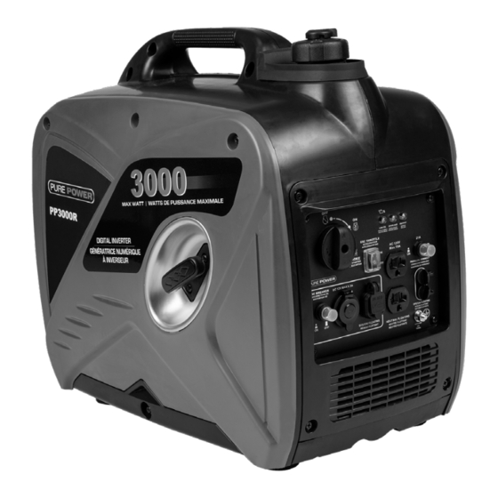
DESCRIPTION DESCRIPTION 1. Carrying handle 2. Fuel tank cap air vent knob 3. Fuel tank cap 4. Control panel 5. Recoil starter 6. Oil filler cap 7. Louver 8. Muffler 9. Spark plug maintenance cover... -
Page 11: Control Panel
DESCRIPTION CONTROL PANEL CONTROL PANEL... -
Page 12: Control Function
CONTROL FUNCTION 3-IN-1 SWITCH KNOB (1) Engine switch\fuel valve “OFF” Ignition circuit and Fuel is currently switched OFF. The engine will not run. (2) Engine switch\fuel valve\choke “ON” Ignition circuit, Fuel, and Choke are ON. The engine can be started. (3) Engine switch\fuel valve\choke “CHOKE” Ignition circuit and Fuel are ON. Choke is switched off. The engine can be started ONLY if it is already warmed up. OIL WARNING LIGHT (RED) When the oil level falls below the lower level, the oil warning light (1) comes on and then the engine stops automatically. Unless you refill with oil, the engine will not start again. TIP: If the engine stalls or does not start, turn the engine switch to “ON” and then pull the recoil starter. If the oil warning light flickers for a few seconds, the engine oil is insufficient. Add oil and restart. -
Page 13: Overload Indicator Light (Red)
CONTROL FUNCTION OVERLOAD INDICATOR LIGHT (RED) The overload indicator light (1) comes on when an overload of a connected electrical device is detected, the inverter control unit overheats, or the AC output voltage rises. Then, the AC protector will trip, stopping power generation in order to protect the generator and any connected electric devices. The AC pilot light (Green) will go off and the overload indicator light (Red) will stay on, but the engine will not stop running. When the overload indicator light comes on and power generation stops, proceed as follows: 1. Turn off any connected electric devices and stop the engine. 2. Reduce the total wattage of connected electric devices within the rated output. 3. Check for blockages in the cooling air inlet and around the control unit. If any blockages are found, remove. 4. After checking, restart the engine. TIP: The overload indicator light may come on for a few seconds at first when using electric devices that require a large starting current, such as a compressor or a submergible pump. However, this is not a malfunction. AC PILOT LIGHT (GREEN) The AC pilot light (1) comes on when the engine starts and produces power. -
Page 14: Dc Protector
CONTROL FUNCTION DC PROTECTOR The DC protector turns to “OFF” (2) automatically when electric device being connected to the generator is operating and current above the rated flows. To use this equipment again, turn on DC protector by pressing its button to “ON” (1) (1) “ON” Direct current is output. (2) “OFF” Direct current is not output. CAUTION • Reduce the load of the connected electric device below the specified rated output of the generator if the DC protector turns off. If the DC protector turns off again, stop using the device immediately and consult our company authorized dealer. ENGINE SMART CONTROL (ESC) (1) “ON” When the ESC switch is turned to “ON”, the economy control unit controls the engine speed according to the connected load. The results are better fuel consumption and less noise. (2) “OFF” When the ESC switch is turned to“OFF”, the engine runs at the rated r/min(4500r/min) regard-less of whether is a load connected or not. TIP: The ESC must be turned to“OFF”when using electric devices that require a large starting current, such as a compressor of a submergible pump. -
Page 15: Fuel Tank Cap
CONTROL FUNCTION FUEL TANK CAP Remove the fuel tank cap by turning it counterclockwise. FUEL TANK CAP AIR VENT KNOB The fuel tank cap (2) is provided with an air vent knob to (1) stop fuel flow. The air vent knob must be turned to “ON”. This will allow fuel to flow to the carburetor and the engine to run. When the engine is not in use, turn the air vent knob to “OFF” to stop fuel flow. GROUND (EARTH) TERMINAL Ground (Earth) terminal (1) connects the earth line for prevention of electric shock. When the electric device is grounded, always the ground the generator. -
Page 16: Preparation
PREPARATION FUEL DANGER • Fuel is highly flammable and poisonous. Check “SAFETY INFORMATION” carefully before filling. • Do not overfill the fuel tank, otherwise it may overflow when the fuel warms up and expands. • After filling, make sure the fuel tank cap is tightened securely. NOTICE • Immediately wipe off spilled fuel with a clean, dry, soft cloth, since fuel may deteriorate painted surfaces or plastic parts. • Use only unleaded gasoline. The use of leaded gasoline will cause severe damage to internal engine parts. Remove the fuel tank cap and fill the fuel into the tank up to the red level. (1) Red line (2) Fuel level Recommended fuel: Unleaded gasoline Fuel tank capacity: Total: 4.0L (1.06 US gal, 0.88 lmp gal) ENGINE OIL NOTICE • The generator has been shipped without engine oil. Do not start the engine without filling with the sufficient engine oil. 1. Place the generator on a level surface. 2. Remove the screws (1), and then remove the cover (2). -
Page 17: Pre-Operation Check
PREPARATION 3. Remove the oil filler cap (3). 4. Fill the specified amount of the recommended engine oil, and then install and tighten the oil filler cap. 5. Install the cover and tighten the screws. Recommended engine oil: SAE SJ 15W-40 Recommended engine oil grade: API Service SE type or higher Engine oil quantity: 450ml PRE-OPERATION CHECK WARNING • If any item in the Pre-operation check is not working properly, have it inspected and repaired before operating the generator. • The condition of a generator is the owner’s responsibility. Vital components can start to deteriorate quickly and unexpectedly, even if the generator unused. TIP: Pre-operation checks should be made each time the generator is used. Pre-operation check Fuel (See page 16) • Check fuel level in fuel tank. • Refuel if necessary. Engine oil • Check oil level in engine. • If necessary, add recommended oil to specified level. • Check generator for oil leakage. - Page 18 PREPARATION WARNING • Never operate the engine in a closed area or it may cause unconsciousness and death within a short time. Operate the engine in a well ventilated area. • Before starting the engine, do not connect any electric devices. NOTICE • The generator has been shipped without engine oil. Do not start the engine until filled with sufficient engine oil. • Do not tilt the generator when adding engine oil. This could result in overfilling and damage to the engine. TIP: The generator can be used with the rated output load at standard atmospheric conditions. “Standard atmospheric conditions” Ambient temperature 25° Barometric pressure 100kPa Relative humidity 30% The output of the generator varies due to change temperature, altitude (lower air pressure at higher altitude) and humidity. The output of the generator is reduced when the temperature, the humidity and the altitude are higher than standard atmospheric conditions. Additionally, the load must be reduced when using in a confined area, as generator cooling is affected.
-
Page 19: Operation
OPERATION STARTING THE ENGINE 1. Turn the ESC switch to “OFF” (1). 2. Turn the air vent knob to “ON” (2). 3. Turn the 3-in-1 switch to “CHOKE” (3), a. Ignition circuit is switched on. b. Fuel is switched on. c. Choke is switched off TIP: The choke is not required to start a warm engine. Push the choke knob in to the position “ON”. 4. Pull slowly on the recoil starter until it is engaged, then pull it briskly. TIP: Grasp the carrying handle firmly to prevent the generator from falling over when pulling the recoil starter. 5. After the engine starts, warm up the engine until the engine does not stop when the choke knob is returned to the “ON” position (4). TIP: When starting the engine, with the ESC “ON”, and there is no load on the generator: • In ambient temperature below 0°C (32°F), the engine will run at the rated r/min (4500r/min) for 5 minutes to warm up the engine. • In ambient temperature below 5°C (41°F), the engine will run at the rated r/min (4500r/min) for 3 minutes to warm up the engine. • The ESC unit operates normally after the above time period, while the ESC is “ON”. -
Page 20: Stopping The Engine
OPERATION STOPPING THE ENGINE TIP: Turn off any electric devices. 1. Turn the ESC to “OFF” (1). 2. Disconnect any electric devices. 3. Turn the 3 in 1 switch to “OFF” (2), a. Ignition circuit is switched off. b. Fuel is switched off. 4. Turn the fuel tank cap air vent knob to “OFF” (3) after the engine has completely cooled down. -
Page 21: Alternating Current (Ac) Connection
OPERATION ALTERNATING CURRENT (AC) CONNECTION WARNING • Be sure any electric devices are turned off before plugging them in. NOTICE • Be sure all electric devices including the lines and plug connections are in good condition before connection to the generator. • Be sure the total load is within generator rated output. • Be sure the receptacle load current is within receptacle rated current. • The generator (STATOR WINDING) is isolated from the AC receptacle ground pin. • Electrical devices that require a grounded receptacle pin connection will not function if the receptacle ground pin is not functional. TIP: Make sure to ground (Earth) the generator. When the electrical device is grounded, the generator must also be grounded. 1. Start the engine. 2. Turn the ESC to “OFF”. 3. Plug in to AC receptacle. 4. Make sure the AC pilot light is on. 5. Turn on any electric devices. TIP: The ESC must be turned to “OFF” to increase engine speed to rated rpm. If the generator is connected to multiple loads or electricity consumers, please remember to first connect the one with the high- est starting current and last connect the one with the lowest starting current. BATTERY CHARGING TIP: • The generator DC rated voltage is 12V. • Start the engine first, and then connect the generator to the battery for charging. • Before starting to charge the battery, make sure that the DC protector is turned on. - Page 22 OPERATION NOTICE • Be sure the ESC is turned off while charging the battery. • Be sure to connect the red battery charger lead to the positive (+) battery terminal ,and connect the black lead to the negative (-) battery terminal. Do not reverse these positions. • Connect the battery charger leads to the battery terminals securely so that they are not disconnected due to engine vibration or other disturbances. • Charge the battery in the correct procedure by following instructions in the owner’s manual for the battery. • The DC protector turns off automatically if current above the rated flows during battery charging. To restart charging the battery, turn the DC protector on by pressing its button to “ON”. If the DC protector turns off again, top charge the battery immediately and consult our company authorized dealer. TIP: • Follow instructions in the owner’s manual for the battery to deter- mine the end of battery charging. • Measure the specific gravity of electrolyte to determine if the bat- tery is fully charged. At full charge, the electrolyte specific gravity is between 1.26 and 1.28. • It is advisable to check the specific gravity of the electrolyte at least once every hour to prevent overcharging the battery. WARNING • Never smoke or make and break connections at the battery while charging. Sparks may ignite the battery gas. • Battery electrolyte is poisonous and dangerous, causing severe burns, etc. contains sulfuric (sulphuric) acid. Avoid contact with skin, eyes or clothing. • Antidote: EXTERNAL: Flush with water. INTERNAL: Drink large quantities of water or milk. Follow with ...
-
Page 23: Application Range
OPERATION APPLICATION RANGE When using the generator, make sure the total load is within rated output of a generator. Otherwise, generator damage may occur. Power 0.8-0.95 0.4-0.75 Factor (Efficiency 0.85) Rated 1,600W 1,280W 544W Rated output voltage 12V power TIP: • Application wattage indicates when each device is used by itself. • The simultaneous usage of AC and DC power is possible but total wattage should not exceed the rated output. Generator rated output 1,600W Frequency Power factor 1,600W 1,280W 96W (12V/8.3A) The overload indicator (1) comes on when total wattage exceeds the application range. (See page 11 for more details.) - Page 24 OPERATION NOTICE • Do not overload. The total load of all electrical appliances must not exceed the supply range of the generator. Overloading will damage the generator. • When supplying precision equipment, electronic controllers, PCs, Electronic computers, microcomputer based equipment or bat- tery chargers, keep the generator a sufficient distance away to prevent electrical interference from the engine. Also ensure that electrical noise from the engine does not interfere with any other electrical devices located near the generator. • If the generator is to supply medical equipment, advice should first be obtained from the manufacturer, a medical professional or hospital. • Some electrical appliances or general-purpose electric motors have High starting currents, and cannot therefore be used, even if they lie within the supply ranges given in the above table. Consult the equipment manufacturer for further advice.
-
Page 25: Maintenance
MAINTENANCE The engine must be properly maintained to ensure its operation is safe,economical and trouble-free, as well as eco-friendly. In order to keep your gasoline engine in good working condition, it must be periodically serviced. The following maintenance schedule and routine inspection procedures must be carefully followed: Items Frequency Each time First 1 Thereafter, Every year month or every 3 or every first 20hrs months or 100hrs of of operation every 50hrs operation of operation Engine oil Check- Refill Replace Reduction Oil level gear oil check (if equipped) Replace... - Page 26 MAINTENANCE NOTICE • If the gasoline engine frequently works under high temperature or heavy load, change the oil every 25 hours. • If the engine frequently work under dusty or other severe circumstances, clean the air filter element every 10 hours; If necessary, change the air filter element every 25 hours. • The maintenance period and the exact time (hour), the one which comes first should govern. • If you have missed the scheduled time to maintain your engine, do it as soon as possible. WARNING • Stop the engine before servicing. Put the engine on a level surface and remove the spark plug cap to prevent the engine from starting. • D o not operate the engine in a poorly ventilated room or other enclosed area. Be sure to keep good ventilation in working area. The exhaust from the engine may contain poisonous CO, inhalation can cause shock, unconsciousness and even death.
-
Page 27: Spark Plug Inspection
MAINTENANCE SPARK PLUG INSPECTION The spark plug is important engine components, which should be checked periodically. 1. Remove the cap (1), and use the tool (3) remove the spark plug cap (2), and Insert the tool (5) through the hole from the outside of the cover. 2. Insert the handlebar (4) into the tool (5) and turn it counterclockwise to remove the spark plug. 3. Check for discoloration and remove the carbon. The porcelain insulator around the center electrode of spark plug should be a medium-to-light tan color. 4. Check the spark plug type and gap. Standard Spark Plug: TORCH-A5RTC/E6TC/E6RTC Spark Plug Gap: 0.6-0.7mm (0.024-0.028in) TIP: The spark plug gap should be measured with a wire thickness gauge and, If necessary, adjusted to specification. 5. Install the spark plug. Spark Plug Torque: 12.5 N*m (1.25 kgf*m, 9 lbf*ft) TIP: If a torque wrench is not available when installing a spark plug, a good estimate of the correct torque is 1/4-1/2 turn past finger tight. However, the spark plug should be tightened to the specified torque as soon as possible. 6. Install the spark plug cap and spark plug cover. -
Page 28: Carburetor Adjustment
MAINTENANCE CARBURETOR ADJUSTMENT The carburetor is a vital part of the engine. Adjusting should be left to our company authorized dealer with the professional knowledge, specialized date, and equipment to do so properly. ENGINE OIL REPLACEMENT WARNING • Avoid draining the engine oil immediately after stopping the engine. The oil is hot and should be handled with care to avoid burns. 1. P lace the generator on a level surface and warm up the engine for several minutes. The stop the engine and turn the 3 in 1 switch knob, fuel tank cap air vent knob to “OFF”. 2. Remove the screws (1) and then remove the cover (2). 3. Remove the oil filler cap (3). 4. Place an oil pan under the engine. Tilt the generator to drain the oil completely. 5. Replace the generator on a level surface. NOTICE • Do not tilt the generator when adding engine oil. This could result in overfilling and damage to the engine. ... -
Page 29: Air Filter
MAINTENANCE 6. Add engine oil to the upper level. Recommended engine oil: SAE SJ 15W-40 Recommended engine oil grade: API Service SE type or higher Engine oil quantity: 0.35L 7. Wipe the cover clean, and wipe up any spilled oil. NOTICE • Be sure no foreign material enters the crankcase. 8. Install the oil filler cap. 9. Install the cover and tighten the screws. AIR FILTER 1. Remove the screws (1), and then remove the cover (2). 2. Remove the screw (3) and then remove the air filter case cover (4). 3. Remove the foam element (5). 4. Wash the foam element in solvent and dry it. 5. Oil the foam element and squeeze out excess oil. The foam element should be wet but not dripping. NOTICE • Do not wring out the foam element when squeezing it. This could cause it to tear. 6. Insert the foam element into the air filter case. TIP: Be sure the foam element sealing surface matches the air filter so there is no air leak. -
Page 30: Muffler Screen And Spark Arrester
MAINTENANCE The engine should never run without the foam element; excessive piston and cylinder wear may result. 7. Install the air filter case cover in its original position and tighten the screw. 8. Install the cover and tighten the screws. MUFFLER SCREEN AND SPARK ARRESTER WARNING • The engine and muffler will be very hot after the engine has been run. Avoid touching the engine and muffler while they are still hot with any part of your body or clothing during inspection or repair. 1. Remove the screws (1), and then pull outward on the areas of the cover (2) shown. 2. Loosen the bolt (3) and then remove the muffler cap (4), the muffler screen (5) and spark arrester (6). 3. Clean the carbon deposits on the muffler screen and spark arrester using a wire brush. NOTICE • When cleaning, use the wire brush lightly to avoid damaging or scratching of muffler screen and spark arrester. 4. Check the muffler screen and spark arrester. Replace them if ... -
Page 31: Fuel Tank Filter
MAINTENANCE TIP: Align the spark arrester projection (7) with the hole (8) in the muffler pipe. 6. Install the muffler screen and the muffler cap. 7. Install the cover and tighten the screws. FUEL TANK FILTER WARNING • Never use the gasoline while smoking or in the vicinity of an open flame. 1. Remove the fuel tank cap and filter. 2. Clean the filter with gasoline. 3. Wipe the filter and install it. 4. Install the fuel tank cap. Be sure the fuel tank cap is tightened securely. FUEL FILTER 1. Remove the screws (1), and then remove the cover (2), and drain the fuel (3). 2. Hold and move up the clamp (4), then take off the hose (5) from the tank. 3. Take out the fuel filter (6). 4. Clean the filter with gasoline. 5. Dry the filter and put it back into tank. 6. Install the hose and clamp, then open the fuel valve to check for leaks. 7. Install the cover and tighten the screws. -
Page 32: Storage
STORAGE Long term storage of your machine will require some preventive procedures to guard against deterioration. DRAIN THE FUEL 1. Turn the 3-in-1 switch to “OFF” (1) . 2. Remove the fuel tank cap, remove the filter . Extract the fuel from the fuel tank into an approved gasoline container. Then, install the fuel tank cap. WARNING • Fuel is highly flammable and poisonous. Check “SAFETY INFORMATION” carefully (See page 6). NOTICE • Immediately wipe off spilled fuel with a clean, dry, soft cloth, since fuel may deteriorate painted surfaces or plastic parts. 3. Start the engine (See Page 19) and leave it running until it stops. The engine stops in approx. 20 minutes time by running out of fuel. TIP: Do not connect with any electrical devices. (unloaded operation) Duration of the running engine depends on the amount of the fuel left in the tank. 4. Remove the screws, and then remove the cover. 5. Drain the fuel from the carburetor by loosening the drain screw on the carburetor float chamber. 6. Turn the 3-in-1 switch to “OFF”. 7. Tighten the drain screw. -
Page 33: Engine
TROUBLESHOOTING 8. Install the cover and tighten the screws. 9. Turn the fuel tank cap air vent knob to “OFF” after the engine has completely cooled down. ENGINE Perform the following steps to protect the cylinder, piston ring, etc. from corrosion. 1. Remove the spark plug, pour about one tablespoon of SAE 10W-30 into the spark plug hole and reinstall the spark plug. Recoil start the engine by turning over several times (with 3-in-1 switch knob off) to coat the cylinder walls with oil. 2. Pull the recoil starter until you feel compression. Then stop pulling. (This prevents the cylinder and valves from rusting). 3. Clean exterior of the generator. Store the generator in a dry, well- ventilated place, with the cover placed over it. TROUBLESHOOTING Engine won’t start 1. Fuel systems • No fuel supplied to combustion chamber. • No fuel in tank…Supply fuel. • Fuel in tank….Fuel tank cap air vent knob and fuel cock knob to “ON” • Clogged fuel filter …. Clean fuel filter. • Clogged carburetor…. Clean carburetor. 2. Engine oil system Insufficient • Oil level is low…. Add engine oil. 3 . Electrical systems • Put the 1 in 3 switch to “CHOKE” and pull the recoil starter Poor spark. • Spark plug dirty with carbon or wet … Remove carbon or wipe spark plug dry. -
Page 34: Generator Won't Produce Power
SPECIFICATIONS GENERATOR WON’T PRODUCE POWER • Safety device (DC protector) to “OFF”…. Press the DC protector to “ON”. • The AC pilot light (Green) goes off …. Stop the engine, then restart. SPECIFICATIONS Item PP3000R Generator Type Silent Inverter Rated frequency (Hz) Rated voltage (v) Rated output power (kW) Max output power (kW) Generator Power Factor Charging Voltage (DC)(V) Charging Current (DC)(A) Overload Protect (DC) Non-fuse Protector Phase Single Engine R80-i MZ80-20i Single cylinder, 4-stroke, forced Engine type air cooling, OHV Displacement (cc) Fuel type Unleaded Gasoline Fuel tank capacity (L) - Page 35 WIRING DIAGRAM...
-
Page 36: Parallel Function
PARALLEL FUNCTION Instructions: First, connect the 2 inverters with 2 parallel cables as per the drawing above, and then start the inverters one at a time. At this time, the total rated power will be 6000W. Note: Ensure the cables are connected to the inverters correctly. If they are connected incorrectly, the inverters will not output any power and will need to be switched off and then on again after they are correctly connected. - Page 37 WARRANTY CALIFORNIA AND FEDERAL EXHAUST AND EVAPORATIVE EMISSIONS CONTROL WARRANTY STATEMENT YOUR WARRANTY RIGHTS AND OBLIGATIONS The California Air Resources Board, the United States Environmental Protection Agency and Chongqing Rato Technology Co., Ltd. (Rato), are pleased to explain the exhaust and evaporative (“emissions”) control system warranty on your 2019/2020 small off-road engine/equipment. In California, new equipment that use small off-road engines must be designed, built, and equipped to meet the State’s stringent anti-smog standards. Rato must warrant the emissions control system on your small off-road engine/equipment for the period listed below provided there has been no abuse, neglect or improper maintenance of your small off-road engine/equipment leading to the failure of the emissions control system. Your emissions control system may include parts such as the carburetor or fuel-injection system, the ignition system, catalytic converter, fuel tanks, fuel lines (for liquid fuel and fuel vapors), fuel caps, valves, canisters, filters, clamps and other associated components. Also included may be hoses, belts, connectors, and other emission-related assemblies. Where a warrantable condition exists, Rato will repair your small off-road engine/equipment at no cost to you including diagnosis, parts and labor. MANUFACTURER’S WARRANTY COVERAGE The exhaust and evaporative emissions control system on your small off-road engine/equipment is warranted for two years. If any emissions- related part on your small off-road engine/equipment is defective, the part will be repaired or replaced by Rato. OWNER’S WARRANTY RESPONSIBILITIES As the small off-road engine/equipment owner, you are responsible for performance of the required maintenance listed in your owner’s manual. Rato recommends that you retain all receipts covering maintenance on your small off-road engine/equipment, but Rato cannot deny warranty ...
- Page 38 WARRANTY You are responsible for presenting your small off-road engine/equipment to a Rato distribution center or service center as soon as the problem exists. The warranty repairs shall be completed in a reasonable amount of time, not to exceed 30 days. If you have any questions regarding your warranty rights and responsibilities, you should contact BE POWER EQUIPMENT at 1-800- 663-8331 (free phone) or Email at info@bepressure.com DEFECTS WARRANTY REQUIREMENTS A - The warranty period begins on the date the small off-road engine/ equipment is delivered to an ultimate purchaser. B - General Emissions Warranty Coverage. Rato warrants to the ultimate purchaser and each subsequent owner that the engine or equipment is: 1. Designed, built, and equipped so as to conform with all applicable regulations adopted by the Air Resources Board; and 2. Free from defects in materials and workmanship that causes the failure of a warranted part for a period of two years. C - The warranty on emission-related parts will be interpreted as follows: 1. Any warranted part that is not scheduled for replacement as required maintenance in the written instructions must be warranted for the warranty period defined in Subsection (b)(2). If any such part fails during the period of warranty coverage, it must be repaired or replaced by Rato according to Subsection (4) below. Any such part repaired or replaced under the warranty must be warranted for the remaining warranty period. 2. Any warranted part that is scheduled only for regular inspection in the written instructions must be warranted for the warranty period defined in Subsection (b)(2). A statement in such written instructions to the effect of “repair or replace as necessary” shall advise owners of the warranty coverage for emissions related parts. Replacement within the warranty period is covered by the warranty and will not reduce the period of warranty coverage. Any such part repaired or replaced under warranty must be warranted for the remaining warranty period. 3. Any warranted part that is scheduled for replacement as required maintenance in the written instructions must be warranted for the period of time prior to the first scheduled replacement point for that part. If the part fails prior to the first scheduled replacement, the part must be repaired or replaced by Rato according to Subsection (4) ...
- Page 39 WARRANTY replacement point for the part. 4. Repair or replacement of any warranted part under the warranty provisions must be performed at no charge to the owner at a warranty station. 5. Notwithstanding the provisions of Subsection (4) above, warranty services or repairs must be provided at distribution centers that are franchised to service the subject engine/equipment. 6. The owner must not be charged for diagnostic labor that leads to the determination that a warranted part is in fact defective, provided that such diagnostic work is performed at a warranty station. 7. Rato is liable for damages to other engine/equipment components proximately caused by a failure under warranty of any warranted part. 8. Throughout the emissions control system’s warranty period set out in subsection (b)(2), Rato must maintain a supply of warranted parts sufficient to meet the expected demand for such parts and must obtain additional parts if that supply is exhausted. 9. Manufacturer-approved replacement parts that do not increase the exhaust or evaporative emissions of the engine or emissions control system must be used in the performance of any warranty maintenance or repairs and must be provided without charge to the owner. Such use will not reduce the warranty obligations of Rato. 10. A dd-on or modified parts that are not exempted by the Air Resources Board may not be used. The use of any non-exempted add-on or modified parts will be grounds for disallowing a warranty claim. Rato will not be liable to warrant failures of warranted parts caused by the use of a non-exempted add-on or modified part. 11. R ato issuing the warranty shall provide any documents that describe that warranty procedures or policies within five working days of request by the Executive Officer. D - Emission Warranty Parts List for Exhaust 1. Fuel Metering System •...
- Page 40 WARRANTY • EGR valve body, and carburetor spacer if applicable. • EGR rate feedback and control system. 5. Air Injection System • Air pump or pulse valve. • Valves affecting distribution of flow. • Distribution manifold. 6. Catalyst or Thermal Reactor System • Catalytic converter. • Thermal reactor. • Exhaust manifold. 7. Particulate Controls • Traps, filters, precipitators, and any other device used to capture particulate vemissions. 8. Miscellaneous Items Used in Above Systems • Electronic controls. • Vacuum, temperature, and time sensitive valves and switches. • Hoses, belts, connectors, and assemblies. E - Emission Warranty Parts List for Evap 1. Fuel Tank 2. Fuel Cap 3. Fuel Lines (for liquid fuel and fuel vapors) 4. ...
- Page 41 NOTES...
- Page 42 If you need assistance with the assembly or operation of your Generator please call 1-866-770-1711 WWW.PUREPOWEREQUIPMENT.COM...
Need help?
Do you have a question about the PP3000R and is the answer not in the manual?
Questions and answers