Table of Contents
Advertisement
Available languages
Available languages
Quick Links
SISTEMAS VRV UD. INTERIOR
DE 2ª GENERACIÓN
CONDUCTOS ALTA PRESIÓN
HIGH PRESSURE DUCT TYPE VRF
SYSTEM 2ND GEN INDOOR UNIT
Gama CND
MANUAL DE
INSTRUCCIONES
INSTRUCTION MANUAL
GUIDE D'UTILISATION
Escanee para ver este manual en otros idiomas y actualizaciones
Scan for manual in other languages and further updates
MANUAL D'INSTRUÇÕES
Manuel dans d'autres langues et mis à jour
Manual em outras línguas e actualizações
V.2
Advertisement
Chapters
Table of Contents

Related Manuals for EAS Electric Gama CND

Summary of Contents for EAS Electric Gama CND
- Page 1 SISTEMAS VRV UD. INTERIOR DE 2ª GENERACIÓN CONDUCTOS ALTA PRESIÓN HIGH PRESSURE DUCT TYPE VRF SYSTEM 2ND GEN INDOOR UNIT Gama CND MANUAL DE INSTRUCCIONES INSTRUCTION MANUAL GUIDE D'UTILISATION Escanee para ver este manual en otros idiomas y actualizaciones Scan for manual in other languages and further updates MANUAL D'INSTRUÇÕES...
-
Page 3: Table Of Contents
Español Contenido 1. Antes de la instalación ..............3 • Asegúrese de que el cableado de alimentación, comunicación y de control estén rectos y nivelados cuando trabaje en las conexiones, y que la cu- 2. Elegir un sitio para la instalación ............3 bierta de la caja eléctrica esté... - Page 4 Donde haya grandes fluctuaciones de voltaje. Si se hace funcionar la unidad con un sistema de suministro de energía que tenga grandes fluctuaciones de vol- taje reducirá la vida útil de los componentes electrónicos y provocará fallos del sistema de control de la unidad. Donde haya un riesgo de fuga de gases inflamables.
-
Page 5: Antes De La Instalación
1. Antes de la instalación 3. Instalación de la unidad interior 1. Determine por donde pasar el equipo hasta el sitio de instalación. Asegúrese de que solo se utilicen los componentes especificados para los trabajos de instalación. 2. Primero rompa los sellos y desempaquete el equipo. A continuación, para mover el equipo sujételo por los cuatro asideros de los ganchos. - Page 6 Chasis de acero Cuidado • Todos los pernos deben ser de acero al carbono de alta calidad (con Ajuste y use directamente una varilla de acero superficie galvanizada u otro tratamiento de prevención de oxida- en ángulo para soporte. ción) o de acero inoxidable. •...
- Page 7 3.3 Dimensiones 3.3.1 Dimensiones de instalación de los pernos de elevación y tamaño de la ubicación de la tubería de conexión (unidades: mm) Unidad: mm 7,1~11,2 kW Imagen 3.7...
- Page 8 Unidad: mm 14,0~16,0 kW Imagen 3.8...
- Page 9 Unidad: mm 20,0~28,0 kW Imagen 3.9...
- Page 10 Unidad: mm Unit: mm 40.0~56.0kW Repair hole Figure 3.10 Imagen 3.10...
-
Page 11: Instalación De Las Tuberías De Refrigerante
Antes de instalar el tapón del casquillo en el casquillo de la tubería, apli- 4. Instalación de las tuberías de refrigerante que un poco de aceite refrigerante en el mismo (tanto por dentro como por 4.1 Requisitos de diferencia de longitud y nivel para las conexiones de las fuera), y luego gírelo tres o cuatro veces antes de apretar el tapón. -
Page 12: Instalación De Las Tuberías De Descarga De Agua
9. Instale el codo de almacenamiento de agua. 5. Instalación de las tuberías de descarga de agua 5.1 Instalación de las tuberías de descarga de agua para la unidad (1) Para un conducto de descarga de agua conectado a la bandeja de drenaje interior principal en la unidad interior, la tubería de descarga de agua debe incluir 1. -
Page 13: Instalación Del Conducto De Aire
6. Instalación del conducto de aire 6.1 Diseño e instalación de tuberías (1) Para evitar el suministro de aire por cortocircuito, las tuberías para la salida de aire y los conductos de retorno de aire no deben estar demasiado cerca. (2) La unidad interior no tiene un filtro de aire instalado. - Page 14 Seleccione la presión estática externa (ESP) adecuada de acuerdo con las condiciones reales de instalación. De lo contrario, puede causar algunos pro- blemas. • Si el conducto de conexión es largo y el ajuste ESP es pequeño, el flujo de aire será...
-
Page 15: Cableado Eléctrico
7.2 Especificaciones del cableado eléctrico 7. Cableado eléctrico 220-240 V~50Hz Atención Conmutador (disyuntores 220-240 V~50/60 Hz para cableado y protec- Fuente de alimentación ción de sobreintensidad) Todas las piezas, materiales y trabajos eléctricos suministrados deben Unidad interior cumplir con las reglamentaciones locales. Disyuntores con fuga de corriente Use solo cables de cobre. - Page 16 Unidad interior 1 Unidad interior 2 Unidad interior n (n<=16) Atención Consulte las leyes y normativas locales para decidir las dimensiones de los cables de alimentación y el cableado. Contacte con un profesional para seleccionar e instalar el cableado. 7.3 Cableado de comunicación Use solo cables blindados para el cableado de comunicación.
-
Page 17: Configuración En El Emplazamiento De La Instalación
8. Configuración en el emplazamiento de la instalación SW1_2 8.1 Ajustes de capacidad Presión estática externa 1 Configure el conmutador DIP de la PCB en la caja de control eléctrico interior [ 00 ] para atender diferentes usos. Una vez finalizada la configuración, asegúrese de haber cortado el suministro eléctrico principal y luego encienda la unidad. -
Page 18: Prueba De Funcionamiento
9. Prueba de funcionamiento SW7_1 9.1 Puntos a tener en cuenta antes de la prueba de funcionamiento Reservado [ 0 ] 1) Las unidades interiores y exteriores están instaladas correctamente; 2) Las tuberías y el cableado son correctos; SW7_2 3) No hay fugas en el sistema de tuberías de refrigerante; 4) La descarga de agua es fluida;... - Page 19 Manual de uso • Deseche esta unidad correctamente y de acuerdo con las normativas lo- cales. Si los equipos eléctricos se desechan en vertederos, las sustancias peligrosas pueden filtrarse al subsuelo y entrar en la cadena alimenticia. En este manual se indican dos símbolos de precaución: •...
-
Page 20: Nombres De Las Partes
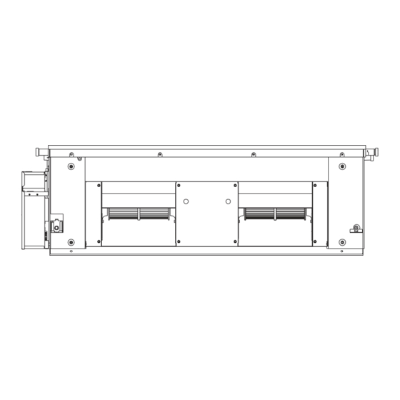
10. Nombres de las partes La imagen que se muestra arriba es solo para referencia y puede ser ligera- mente diferente del producto real. Lamas de la salida de aire (orientables) Para el ajuste in situ en tres o dos direcciones, póngase en contacto con el distribuidor local. -
Page 21: Mantenimiento
12. Funcionamiento y rendimiento del equipo de aire acondicionado El rango de temperatura de funcionamiento bajo el cual la unidad funciona de manera estable se indica en la tabla siguiente. 13. Mantenimiento Modo Temperatura interior 17-32 °C Refrigera- Cuidado Si la humedad interior supera el 80%, se puede formar ción condensación en la superficie de la unidad. -
Page 22: Síntomas Que No Son Fallos
14. Síntomas que no son fallos Los síntomas siguientes pueden experimentarse durante el funcionamiento normal de la unidad y no se consideran fallos. Nota: Si no está seguro de si se ha producido un fallo, póngase en contacto con su proveedor o ingeniero de Afloje los pernos y Imagen 13.1 servicio de inmediato. - Page 23 15.2 Solución de problemas de la unidad Síntoma Causas posibles Pasos para solucionar problemas Se ha producido un corte en el suministro Espere a conectar que se restablezca el suministro eléctrico (se ha cortado el suministro eléctrico a eléctrico. las instalaciones). Ponga en marcha el equipo.
- Page 24 15.3 Solución de problemas del mando a distancia Atención: Determinados pasos para la solución de problemas que un técnico profesional puede realizar al investigar un error se describen en este manual del usuario solo como referencia. No intente solucionar el problema usted mismo, acuda a un técnico profesional para que investigue y solucio- ne el problema.
- Page 25 15.4 Códigos de error Con la excepción de un fallo de conflicto de modo, contacte con su proveedor o ingeniero de servicio si alguno de los códigos de error listados en la siguiente tabla se muestran en la pantalla de la unidad. Si se muestra el fallo de conflicto de modo y persiste, contacte con su proveedor o ingeniero de servicio.
- Page 26 CONDICIONES DE LA GARANTÍA EAS ELECTRIC ofrece una garantía de reparación contra todo defecto de funcionamiento proveniente de la fabricación, incluyendo mano de obra y piezas de recambio, en los plazos y términos indicados a continuación: 3 años: Gama Doméstica, Gama Comercial, VRV de uso doméstico, M-Thermal Monoblock y Biblock, Fan Coils de uso doméstico, Acumuladores aerotérmicos de ACS, Bombas de Piscina, Minichillers de uso...
- Page 27 English Contents • Use only electrical cables that fulfil the specifications. All wiring on Installaion Manual................1 site must be carried out in accordance with the connection diagram Accessories..................2 attached to the product. Make sure that there are no external forces 1.
-
Page 28: Installaion Manual
• When mounting the indoor and outdoor units, make sure the power cord is installed at a distance of at least 1 m away from any TV or radio so as to prevent noise or interference with the images. • The refrigerant required for the installation is R410A. Make sure the refrigerant is correct before installation. Incorrect refrigerant may cause the unit to malfunction. -
Page 29: Before Installation
Expansion hook To purchase based on actual For installation of project requirements. anchor indoor unit. To purchase based on actual For installation of Mounting hook project requirements. indoor unit. To purchase based on actual To purchase based on actual Tie for connecting wire project requirements. - Page 30 Steel framework Caution • All bolts should be made from high quality carbon steel (with Directly set and use an angled steel rod for support. galvanized surface or other rust prevention treatment) or stainless steel. • How the ceiling should be handled will differ with the type of building.
- Page 31 3.3 Dimensions 3.3.1 Installation dimensions of lifting bolts and location size of connecting piping (unit: mm) Unit: mm 7.1~11.2kW Figure 3.7...
- Page 32 Unit: mm 14.0~16.0kW Figure 3.8...
- Page 33 Unit: mm 20.0 28.0kW 342(W) 68.5 Figure 3.9...
- Page 34 Unit: mm 40.0~56.0kW Repair hole Figure 3.10...
-
Page 35: Refrigerant Piping Installation
Before the socket cap is installed on the pipe socket, apply some 4. Refrigerant Piping Installation refrigerant oil on the socket (both inside and outside), and then rotate 4.1 Length and Level Difference Requirements for the Piping it three or four times before you tighten the cap. See Figure 4.3. Connections to the Indoor and Outdoor Units Apply refrigerant oil The length and level difference requirements for the refrigerant piping... -
Page 36: Water Discharge Piping Installation
9. Install the water storage elbow. 5. Water Discharge Piping Installation 5.1 Water Discharge Piping Installation for Indoor Unit (1) For a water discharge duct connected to the main drain pan in the indoor unit, the water discharge piping must include a water 1. -
Page 37: Air Duct Installation
6. Air Duct Installation 6.1 Piping Design and Installation (1) In order to prevent short-circuit air delivery, the piping for air outlet and air return ducts must not be too close. (2) The indoor unit does not have an air filter installed. The air filter must be installed at a location like an air inlet where it can be easily maintained. (Without an air filter, dust particles may stick to the air heat exchanger which will make the air conditioner prone to failures and water leakage.) (3) Before installing the air duct, ensure that the static pressure of the air duct is within the permitted range of the indoor unit (see section 6.2). - Page 38 11.2kW 200Pa 190Pa 180Pa 170Pa 160Pa 150Pa 140Pa 130Pa 120Pa 110Pa 100Pa(default) 90Pa 80Pa 70Pa 60Pa 50Pa 30Pa 1340 1390 1440 1490 1540 1590 1640 1690 1740 1790 1840 1890 Air flow (m 14.0kW 200Pa 190Pa 180Pa 170Pa 160Pa 150Pa 140Pa 130Pa 120Pa...
- Page 39 20.0/25.0/28.0kW 250Pa 230Pa 210Pa 200Pa 190Pa 180Pa 170Pa(default) 160Pa 150Pa 140Pa 130Pa 120Pa 110Pa 100Pa 90Pa 80Pa 70Pa 60Pa 50Pa 30Pa 3720 3770 3820 3870 3920 3970 4020 4070 4120 4170 4220 4270 4320 Air flow (m 40-45 KW 400Pa 380Pa 360Pa 340Pa...
- Page 40 Set proper external static pressure (ESP) according to the actual installation Figure 7.2 shows the power supply terminal of the indoor unit. conditions. Otherwise it may cause some problems. If the connecting duct is long and the ESP setting is small, the airflow will be very small, leading to poor performance.
- Page 41 (Connect the shielded end of the shielded Outdoor wire to the electronic controller box sheet unit Table 7.2 Indoor units electrical characteristics metal " " here) Power supply Signalling line Model name (P Q E) between outdoor Volts units Connecting the shielded 7.1kW 0.15 layer of the shielded wire...
-
Page 42: On-Site Configuration
The X1, X2, D1, D2 ports on the sides of the main control board and the 8.2 Address Settings unidirectional communication port (display board side) are for different When this indoor unit is connected to the outdoor unit, the outdoor unit types of wired controllers (see Figure 7.10). -
Page 43: Test Run
8.4 Error Codes and Definitions In heating mode when the set temperature has been reached, the fan operates in a 4 minutes off / 1 minute on repeating cycle Error Content code In heating mode when the set temperature has been reached, the fan operates in an 8 minutes off / 1 minute on repeating cycle Mode conflict... - Page 44 • Do not remove the remote controller’s front or back overs and do not Operation Manual touch the remote controller’s internal components, as doing so can There are two types of precautions as described below: cause injury. If the remote controller stops working, contact your Warning: Failure to comply may lead to death or serious injury.
-
Page 45: Part Names
• This appliance can be used by children aged from 8 years and above and persons with reduced physical, sensory or mental ■ High static pressure duct type capabilities or lack of experience and knowledge if they have been given supervision or instruction concerning use of the appliance in Air Intake a safe way and understand the hazards involved. -
Page 46: Air Conditioner Operations And Performance
13. Adjusting Air Flow Direction 12. Air Conditioner Operations and Performance Since warmer air rises and cooler air falls, the distribution of The operating temperature range under which the unit runs stably are given in warmed/cooled air around a room can be improved by positioning the below table. -
Page 47: Symptoms That Are Not Faults
15. Symptoms That Are Not Faults The following symptoms may be experienced during the normal operation of the unit and are not considered faults. Note: If you are not Loosen the bolts and sure whether a fault has occurred, contact your supplier or service dismantle the filter. - Page 48 16.2 Unit Troubleshooting Symptom Possible causes Troubleshooting steps A power cut has occurred (the power to the Wait for the power to come back on. premises has been cut-off). Power on the unit. This indoor unit forms part of an air conditioning system that has multiple indoor units that are all connected.
- Page 49 16.3 Remote Controller Troubleshooting Warning: Certain troubleshooting steps that a professional technician may perform when investigating an error are described in this owner's manual for reference only. Do not attempt to undertake these steps yourself – arrange for a professional technician to investigate the problem. If any of the following errors occur, power the unit off and contact a professional technician immediately.
- Page 50 16.4 Error Codes With the exception of a mode conflict error, contact your supplier or service engineer if any of the error codes listed in the following table are displayed on the unit's display panel. If the mode conflict error is displayed and persists, contact your supplier or service engineer. These errors should only be investigated by a professional technician.
- Page 51 5 years: Buffer tanks, and compressor (component only) for all units. 7 years (mainland Spain)/3 years (Canary Islands and Balearic Islands): Hot water cylinders (Inter) The warranty of the VRF systems is subject to the study of the principle scheme by the EAS ELECTRIC SMART TECHNOLOGY S.L.U. prescription department.
- Page 52 Toda la documentación del producto Complete documents about the product Documentation plus complète sur le produit Mais documentação do produto EAS ELECTRIC SMART TECHNOLOGY, S.L.U. P.I. San Carlos, Camino de la Sierra, S/N, Parcela 11 03370 Redován (Alicante) - ESPAÑA...
Need help?
Do you have a question about the Gama CND and is the answer not in the manual?
Questions and answers