Table of Contents
Advertisement
Quick Links
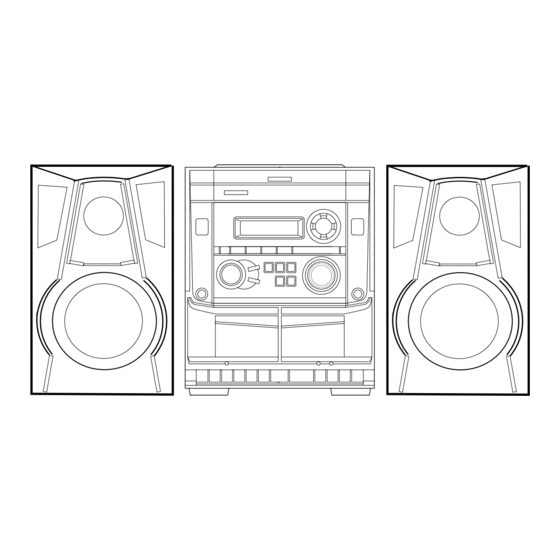
SERVICE MANUAL
COMPACT DISC STEREO
CASSETTE RECEIVER
SYSTEM
NSX-VC18
• This Service Manual is the "Revision Publishing" and replaces "Simple
Manual" NSX-VC18(HR / HT), (S/M Code No. 09-004-429-2T1).
• If requiring information about the CD mechanism, see Service Manual
of AZG-1, (S/M Code No. 09-001-335-3NG).
NSX-VC18
BASIC TAPE MECHANISM : ZZM-2 PR1NM
BASIC CD MECHANISM : AZG-1 VZD3RNDM
CD
SPEAKER
CASSEIVER
CX-NVC18
SX-NBL17
S/M Code No. 09-005-429-2R1
REMOTE
CONTROLLER
RC-ZAS11
HR,HT
Advertisement
Table of Contents

Subscribe to Our Youtube Channel
Related Manuals for Aiwa NSX-VC18HR


Summary of Contents for Aiwa NSX-VC18HR
- Page 1 NSX-VC18 HR,HT SERVICE MANUAL COMPACT DISC STEREO BASIC TAPE MECHANISM : ZZM-2 PR1NM CASSETTE RECEIVER BASIC CD MECHANISM : AZG-1 VZD3RNDM REMOTE SYSTEM SPEAKER CASSEIVER CONTROLLER RC-ZAS11 CX-NVC18 NSX-VC18 SX-NBL17 • This Service Manual is the “Revision Publishing” and replaces “Simple Manual”...
-
Page 2: Specifications
SPECIFICATIONS <FM tuner section> <Compact disc player section> Tuning range 87.5 MHz to 108 MHz Laser Semiconductor laser (λ =780 nm) Usable sensitivity (IHF) 13.2 dBf D-A converter 1 bit dual Antenna terminals 75 ohms (unbalanced) Signal-to-noise ratio 85 dB (1 kHz, 0 dB) Harmonic distortion 0.05 % (1 kHz, 0 dB) <MW tuner section>... -
Page 3: Protection Of Eyes From Laser Beam During Servicing
PROTECTION OF EYES FROM LASER BEAM DURING SERVICING CAUTION This set employs laser. Therefore, be sure to follow carefully Use of controls or adjustments or performance of proce- the instructions below when servicing. dures other than those specified herein may result in hazardous radiation exposure. -
Page 4: Note On Before Starting Repair
NOTE ON BEFORE STARTING REPAIR 1. Forced discharge of electrolytic capacitor of power supply block When repair is going to be attempted in the set that uses relay circuit in the power supply block, electric potential is kept charged across the electrolytic capacitors (C101, 102) even though AC power cord is removed. - Page 5 In such a case, check also if the POWER AMPLIFIER circuit or power supply circuit has any abnormalities or not. 2-2. Regarding reset There are cases that the machine does not work correctly because the MICROCOMPUTER is not reset even though the AC power cord is re-inserted, or the software reset (pressing the STOP key + POWER key) is performed.
-
Page 6: Electrical Main Parts List
ELECTRICAL MAIN PARTS LIST REF. NO. PART NO. KANRI DESCRIPTION REF. NO. PART NO. KANRI DESCRIPTION 87-010-263-080 CAP, ELECT 100-10V 87-010-197-080 CAP, CHIP 0.01 DM 8A-NHZ-601-010 C-IC,M38B57MCH-E244FP 87-010-263-080 CAP, ELECT 100-10V 87-A21-396-010 IC,STK490-040 87-010-247-080 CAP, ELECT 100-50V 87-A21-419-040 C-IC,NJM14558MD-TE2 87-010-406-080 CAP, ELECT 22-50 87-A21-443-040 C-IC,M62495AFP... - Page 7 REF. NO. PART NO. KANRI DESCRIPTION REF. NO. PART NO. KANRI DESCRIPTION C452 87-010-382-080 CAP, ELECT 22-25V C849 87-010-197-080 CAP, CHIP 0.01 DM<HT> C453 87-010-183-080 C-CAP,S 2700P-50 B C851 87-010-197-080 CAP, CHIP 0.01 DM C454 87-010-183-080 C-CAP,S 2700P-50 B C852 87-010-197-080 CAP, CHIP 0.01 DM C455...
- Page 8 REF. NO. PART NO. KANRI DESCRIPTION REF. NO. PART NO. KANRI DESCRIPTION R654 87-A11-144-080 CAP,TC U 0.1-50 K B R790 87-010-197-080 CAP, CHIP 0.01 DM C513 87-016-669-080 C-CAP,S 0.1-25 K B R991 87-010-322-080 C-CAP,S 100P-50 CH C515 87-010-374-040 CAP,E 47-10 M 11L R993 87-010-322-080 C-CAP,S 100P-50 CH...
-
Page 9: Chip Resistor Part Code
CHIP RESISTOR PART CODE Chip Resistor Part Coding Figure Resistor Code Value of resistor Chip resistor Dimensions (mm) Symbol Wattage Type Tolerance Resistor Code Form 1/16W 1005 0.35 1/16W 1608 0.45 1/10W 2125 1.25 0.45 1/8W 3216 0.55 TRANSISTOR ILLUSTRATION S D G E C B E C B... - Page 10 FL (10-BT-224GNK) GRID ASSIGNMENT AND ANODE CONNECTION GRID ASSIGNMENT – –...
- Page 11 ANODE CONNECTION – –...
-
Page 12: Wiring - 1 (Main)
WIRING – 1 (MAIN) <HR> – 12 –... - Page 13 SCHEMATIC DIAGRAM – 1 (MAIN 1 / 2 : AMP SECTION)<HR> – 13 –...
-
Page 14: Schematic Diagram - 2 (Main 2/2 : Tuner Section)
SCHEMATIC DIAGRAM – 2 (MAIN 2/2 : TUNER SECTION)<HR> – 14 –... -
Page 15: Wiring - 2 (Main)
WIRING – 2 (MAIN)<HT> – 15 –... - Page 16 SCHEMATIC DIAGRAM – 3 (MAIN 1 / 2 : AMP SECTION)<HT> – 16 –...
- Page 17 SCHEMATIC DIAGRAM – 4 (MAIN 2/2 : TUNER SECTION)<HT> – 17 –...
-
Page 18: Wiring - 3 (Front)
WIRING – 3 (FRONT) – 18 –... -
Page 19: Schematic Diagram - 5 (Front)
SCHEMATIC DIAGRAM – 5 (FRONT) – 19 –... - Page 20 WIRING – 4 (PT) – 20 –...
-
Page 21: Schematic Diagram - 6 (Pt)
SCHEMATIC DIAGRAM – 6 (PT) – 21 –... -
Page 22: Wiring - 5 (Deck)
WIRING - 5 (DECK) -
Page 23: Ic Block Diagram
IC BLOCK DIAGRAM – 23 –... - Page 24 IC DESCRIPTION IC, M38B57MCH-E244FP Description Pin No. Pin Name I-SIG RDS signal level A/D input. I-HOLD Hold voltage level A/D input. I-SW (CD) CD mecha SW A/D input. I-DISH CD turn-table position check A/D input. I-KEY2 KEY2 A/D input. I-KEY1 KEY1 A/D input.
- Page 25 Pin No. Pin Name Description O-DISH-R CD turn-table reverse turn output. O-DISH-F CD turn-table forward turn output. I-SUBQ Sub code-Q data input. O-CD-CE CD DSP chip enable output. I-WRQ CD WRQ input. (Not used) O-CLK (CD) CD control clock output. (Not used) O-DATA (CD) CD control data output.
- Page 26 ADJUSTMENT <TUNER / DECK> A MAIN C.B TC943 L802 L801 TP4 (DC) L941 TC941 IC801 L942 TP3 (DC) IC301 L953 L952 (CLK) TP8 (LCH) TP1(VT) TP9 (RCH) FFE831 DECK–1 R/P/E, DECK-2 P HEAD B FRONT C.B FL201 TP5 (K-SCAN) IC101 L101 SFR701 –...
- Page 27 < TUNER SECTION > < DECK SECTION > 1. Clock frequency Check 10. Tape Speed Adjustment (DECK 1) Settings : • Test point : TP2 (CLK) Settings : • Test tape : TTA–100 Method : Set to MW 1602kHz and check that the test point is •...
-
Page 28: Mechanical Exploded View
MECHANICAL EXPLODED VIEW 1 / 1 AZG-1 31 30 P.C.B P.C.B HT-SINK PLATE,EARTH ZZM-2 HLDR1 WIRE, P.C.B HLDR2 BINDER PLATE, EARTH MIC CHAS, MAIN – –... -
Page 29: Mechanical Parts List
BVTT+3-6 17 8A-NFA-018-010 REFLECTOR,ECO F 87-723-096-410 QT2+3-10W/O SLOT BL 18 8A-NFZ-008-010 KEY,POWER G 87-721-096-410 QT2+3-10 GLD 19 87-CE3-023-010 BADGE,AIWA 30N SILV H 87-721-097-410 QT2+3-12 GLD 20 8A-NHZ-002-010 PANEL,TRAY H I 87-067-641-010 UTT2+3-8(W/O SLOT)BL 21 8A-NFA-208-010 GUIDE,FL 100-25 ANFA 22 88-913-221-110 FF-CABLE, 13P 1.25 220MM... -
Page 30: Tape Mechanism Exploded View
TAPE MECHANISM EXPLODED VIEW 1 / 1 TERMINAL,LB1 TERMINAL,LB1 – –... -
Page 31: Tape Mechanism Parts List
TAPE MECHANISM PARTS LIST 1 / 1 REF. NO. PART NO. KANRI DESCRIPTION REF. NO. PART NO. KANRI DESCRIPTION 1 8Z-ZM1-254-210 SPR-C,REEL R 36 8Z-ZM1-220-110 LEVER,REC SENSOR 2 8Z-ZM1-225-110 GEAR,REEL R 37 8Z-ZM1-249-010 SPR-T,FR 3 8Z-ZM1-253-110 SPR-C,AUTO SENSOR 38 8Z-ZM1-242-110 SPR-T,FF/REW 4 8Z-ZM1-217-110 LEVER,AUTO SENSOR... - Page 32 SPEAKER DISASSEMBLY INSTRUCTIONS Type.1 Type.4 Insert a flat-bladed screwdriver into the position indicated by the TOOLS arrows and remove the panel. Remove the screws of each speaker 1 Plastic head hammer unit and then remove the speaker units. 2 (() flat head screwdriver 3 Cut chisel How to Remove the PANEL, FR Type.2...
-
Page 33: Accessories / Package List
SPEAKER PARTS LIST SX-NBL17(YJ7SL,YJSC,YJSC9,Y1SL) REF. NO. PART NO. KANRI DESCRIPTION 1 8A-NSB-001-010 PANEL,FR 2 8A-NSB-003-010 GRILLE,FRAME ASSY 3 8Z-NSL-603-010 SPKR, W 120 ACCESSORIES / PACKAGE LIST REF. NO. PART NO. KANRI DESCRIPTION 1 8A-NHZ-901-010 IB,H(ECA)M<EXCEPT HRJSC> 1 8A-NHZ-910-010 IB,H(T)DIT<HRJSC> 2 8Z-NHA-702-010 RC UNIT,RC-ZAS11 3 87-043-115-010 ANT,FEEDER FM... - Page 34 2–11, IKENOHATA 1–CHOME, TAITO-KU, TOKYO 110, JAPAN TEL:03 (3827) 3111 9630472 0251431 Printed in Singapore...
Need help?
Do you have a question about the NSX-VC18HR and is the answer not in the manual?
Questions and answers