Table of Contents
Advertisement
Quick Links
For Your Safety
WARNING: If the information in these
instructions is not followed exactly, a fire or
explosion may result causing property damage,
personal injury, or death.
- Do not store or use gasoline or other flammable vapors
and liquids in the vicinity of this or any other appliance.
- WHAT TO DO IF YOU SMELL GAS
• Do not try to light any appliance.
• Do not touch any electrical switch; do not use any
phone in your building.
• Immediately call your gas supplier from a neighbor's
phone. Follow the gas supplier's instructions.
• If you cannot reach your gas supplier, call the fire
department.
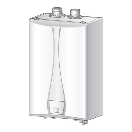
REVOLUTION CONDENSING
HEATING BOILERS
Installation
Manual
Model
VRB-110 VRB-130
Keep this manual near this boiler for future reference
whenever maintance or service is required.
Improper installation, adjustment, alteration, service or
maintenance can cause property damage, personal injury
(exposure to hazardous materials)* or loss of life. Refer to
the user's information manual provided with this boiler.
Installation and service must be performed by a qualified
installer, service agency or the gas supplier (who must
read and follow the supplied instructions before installing,
servicing, or removing this boiler.
This boiler contains materials that have been identified as
carcinogenic, or possibly carcinogenic, to humans).
This boiler must be installed in accordance with local
codes. In the absence of local codes, it must be installed
in compliance with The Federal Manufactured Home
Construction and Safety Stand Title 24 CRF, part 3280 or
CAN/CSA Z240 MH series, mobile home. In the absence
of such standard, The Standard for mobile Homes (ANSI/
NFPA No. 601B-1977).
The installation must conform with local codes or, in
the absence of local codes, the National Fuel Gas Code,
ANSIZ223.1/NFPA 54 and/or CAN/CSA B149.1, Natural
Gas and Propane Installation Code.
WARNING
Advertisement
Table of Contents

Related Manuals for VST VRB-110


Summary of Contents for VST VRB-110
- Page 1 REVOLUTION CONDENSING HEATING BOILERS Installation Manual Model VRB-110 VRB-130 Keep this manual near this boiler for future reference whenever maintance or service is required. For Your Safety WARNING Improper installation, adjustment, alteration, service or WARNING: If the information in these...
-
Page 2: Safety Information
Safety Information The following safety symbols are used in this manual for user's safety. Read this manual carefully and follow all instructions to avoid property damage, fire, explosion, personal injury, or death. Danger Indicates an imminently hazardous situation which, if not avoided, will result in severe injury or death. Warning Indicates a potentially hazardous situation which, if not avoided, will result in injury or death. - Page 3 Warning • Do not store combustibles, such as papers or laundry, near the boiler or venting system. Failure to do so may result in fire or explosion. • Do not store or use gasoline or other flammable liquids near this boiler. Failure to do so may result in fire or explosion.
-
Page 4: Important Note For The State Of Massachusetts
Important Note for the State of Massachusetts NOTICE BEFORE INSTALLATION This appliance must be installed by a licensed plumber or gas fitter in accordance with the Massachusetts Plumbing and Fuel Gas Code 248 CMR Sections 4.00 and 5.00. IMPORTANT: In the State of Massachusetts (248 CMR 4.00 & 5.00) For all side wall horizontally vented gas fueled equipment installed in every dwelling, building or structure used in whole or in part for residential purposes, including those owned or operated by the Commonwealth and where the side wall exhaust vent termination is less than seven (7) feet above finished grade in the area of the venting, including but not limited to decks and porches, the following requirements shall be satisfied. -
Page 5: Table Of Contents
Table of Contents Safety Information ........2 Setting the DIP Switches ......35 Important Note for the State of Connecting the Power Supply ....36 Massachusetts ........... 4 Installation Checklist ....... 37 General Information ........6 Operating the Boiler ........ 40 Included Items .............. -
Page 6: General Information
General Information Included Items Optional Accessories The following items are included with the boiler. Check each of the The following optional accessories are not included with the boiler, following items before installation. but may be necessary for the installation. Check the need for any of the following optional accessories before installation. -
Page 7: Specifications
Specifications The following table shows the specifications for the boiler. Additional specifications about water, gas, electric, and air supplies (venting) appear in each installation section. MODEL VRB-110 VRB-130 Heat Capacity (Input) Space Heating 19,900–110,000 BTU/H 19,900–130,000 BTU/H AFUE Natural Gas (propane) 95.0%(95.0%) -
Page 8: Rating Plate
Rating Plate The gas type and electricity voltage must match the rating plate. Using a diferent gas type and electricity voltage will cause the boiler to malfunction. Danger Before the installation, check the rating plate located on the side of the boiler to ensure that the boiler matches the gas type, gas pressure, water pressure, and electrical supply available in the installation location. -
Page 9: Dimensions
Dimensions Description Diameter Space Heating Return 1" NPT Condensate Outlet 1/2" NPT Space Heating Supply 1" NPT Gas Inlet 3/4" NPT Exhaust Vent 2" Air Intake 2" 5.57" 5.26" 1.8" (141.5 mm) (133.5 mm) (45.7 mm) 5.2" 5.0" 6.3" 1.6" 18.11"... -
Page 10: Components
Components Flue connector Air intake connector Exhaust temperature sensor Burner hood Gas connector Heat Exchanger Cover Gas valve Pressure sensor Air vent Space heating supply Condensate drain Gas inlet Space heating return Installation Manual... - Page 11 Turbo fan assembly Ignition transformer TDR damper Primary heat exchanger Secondary heat exchanger Pressure sensor Air pressure switch PCB assembly Front panel General Information...
-
Page 12: Installing The Boiler
Installing the Boiler Installer Qualifications Access to utilities • Electricity – Close to where the electrical supply enters the building A licensed professional must install and inspect the appliance. A • Water – Close to where the domestic water supply enters the licensed professional is a person who is licensed for the following: building •... - Page 13 Clearances Clean, debris and chemical-free combustion The boiler should be installed in an area that allows for service and maintenance access to utility connections, piping, filters, and traps. • Do not install the boiler in areas where dust and debris may Ensure the following clearances are maintained: accumulate or where combustion air can be contaminated.
- Page 14 Mounting to the wall • The boiler is heavy. Always lift the unit with assistance. Be careful not to drop the boiler while lifting or handling it to To mount the boiler to the wall: avoid bodily injury or damage to the unit. Warning •...
-
Page 15: Installing The System Piping
When installing the VST boiler and keeping the existing pipes, all pipes including the radiator should be cleaned. • VST VRB boiler is intended solely for use in a pressurized closed loop heating system operating with 7-30psi water pressure If you fail to remove the above-mentioned contaminants at the boiler outlet. - Page 16 • It is recommended to use unions for the serviceability of the The VST VRB boiler already has a type of low water cut off (LWCO) device. device that senses the pressure inside of the product. The minimum operating pressure of this device is 7.1psig.
-
Page 17: Connection The Condensate Drain
Connection the Condensate Drain When installing the pressure relief valve, follow the guidelines below. • The discharge capacity of the valve should be greater than or • All condensate must drain and be disposed of according to equal to the maximum pressure rating of the space heating local codes. - Page 18 Filling the Condensate Trap Notice Before operating the boiler, fill the condensate trap with water • If you choose this option, the neutralizing agent must be replaced through the flue connector. The boiler may be severely damaged periodically. Depletion of the neutralizing agent will vary, based on unless filled with water prior to operation.
-
Page 19: System Filling
System Filling Test the Water System Make sure to fill the boiler with water before operating the External Water Fill Connection boiler. Operating the boiler while filling it with water may damage Warning An external make-up water connection is required. the boiler. -
Page 20: Example Of System Applications
Notice VST VRB boiler has an air vent inside the product in order to purge air in the system. Installation Manual... - Page 21 System Application – Zone System with Zone Valves Zone 1 Zone 2 Zone 3 Zone Valve System pump Air Separator Not to exceed 4 pipe Dia or Max. 12" Boiler pump Expansion tank Make-up water System Application – Zone System with Circulators Zone 1 Zone 2 Zone 3...
- Page 22 System Application – DHW System with Indirect Tank Zone 1 Zone 2 Zone 3 Zone Valve System pump Air Separator Expansion tank Make-up water DHW Outlet Thermostat DHW wire TT DHW wire Anti-scald mixing valve TT Heat wire Indirect Tank Thermostat Boiler pump DHW pump...
-
Page 23: Connecting The Gas Supply
Connecting the Gas Supply Gas Pipe Sizing Tables Gas pipe sizing is based on the gas type, supplied gas pressure, pressure drop in the system, and gas line type. The tables below are for reference only (when the gas supply is piping straight to the boiler with no connections to any other gas appliances). For gas pipe sizing, refer to the latest National Fuel Gas code, NFPA 54 and consult the gas pipe manufacturer for actual gas pipe capacities. -
Page 24: Gas Piping
• Leak test the appliance and its gas connection before operating the boiler. • Do not attempt a field conversion without a VST conversion kit. Use the VST conversion kit to convert from natural gas to propane or vice versa. Failure to do so may result in Check for gas leaks at all joints. -
Page 25: Inlet Gas Pressure
Inlet Gas Pressure • The following is a LP gas piping example for the single regulator system Inlet gas pressure should be measured by a licensed professional only. The boiler cannot function properly without Warning sufficient inlet gas pressure. • The boiler must be isolated from the gas supply piping system during any pressure testing of that system at test pressures equal to or more than 0.5 psig. - Page 26 Remove the boiler front cover by loosening the 2 Phillips When the boiler reaches its maximum firing rate, check the screws securing it to the case. inlet gas pressure reading on the manometer. The gas pressure must fall within the ranges specified in "Specifications" on page Tighten the inlet gas pressure screw.
-
Page 27: Installing A Vent
Clause 8.2, 8.3 or 8.4 of Natural Gas and avoid back drafting cold air through the boiler. VST recommends Propane Installation Code, CAN/CSA B149.1 in Canada, as well direct air vent installations when installing the boiler in your attic to as all applicable local building codes and regulations. - Page 28 F IX E D C L O S E D F IX E D C L O S E D VENT TERMINAL AIR SUPPLY INLET AREA WHERE TERMINAL IS NOT PERMITTED Canadian Direct Vent U.S Direct Vent Installations Installations Clearance above grade, veranda, porch, deck or balcony 12 in.
- Page 29 VST warranty. If there is any question about the possibility of back-drafting in the installation location, use a direct venting system for the boiler.
- Page 30 F IX E D C L O S E D F IX E D C L O S E D VENT TERMINAL AIR SUPPLY INLET AREA WHERE TERMINAL IS NOT PERMITTED Canadian Non-Direct Vent U.S. Non-Direct Vent Installations Installations Clearance above grade, veranda, porch, deck or balcony 12 in.
-
Page 31: Vent Pipe Materials
Length Elbows • This boiler has a built-in control to limit the exhaust Reduce the maximum vent temperature to 149°F (65°C). As a result, the VST boiler can length accordingly for each be vented with Schedule 40 PVC. Caution elbow used: •... -
Page 32: Connecting The Vent Clip
Connecting the Vent Clip Vent Termination • Air intake must be protected from any debris. To connect the exhaust vent firmly, must use the vent clip • When connecting the air intake connector and the flue included with boiler. Caution Caution connector with the vent, connecting parts must be sealed with PVC, glue and high temp silicon. - Page 33 Two-pipe sidewall venting Snorkel flue Internal view Exhaust gas 10" (254 mm) min. Intake air Schedule 40 PVC pipe 12" (300 mm) min. 10" min. External view • Maintain 12" (300 mm) min. (18" (450 mm) min. for Canada) clearance above highest-anticipated snow level. Maximum 12"...
- Page 34 Non-concentric sidewall venting Two-pipe vertical venting 36" (900 mm) min. Exhaust gas Intake air 12" (300 mm) min. From any obstruction 10" (254 mm) min. (above, below, left, or right) • Maintain 12" (300 mm) min. (18" (450 mm) min. for Canada) •...
-
Page 35: Setting The Dip Switches
Setting the DIP Switches The boiler has a DIP switch on the main circuit board(PCB) Set the DIP switch appropriately, depending on the installation environment. Switch Function ON: No temperature limit for exhaust gas Temperature limit switch for exhaust gas OFF: Temperature limit for exhaust gas ON: Enable EEP ROM data change EEP ROM data change switch... -
Page 36: Connecting The Power Supply
Connecting the Power Supply When connecting the power supply, follow these guidelines: Improperly connecting the power supply can result in electrical shock and electrocution. Follow all applicable • Do not connect the electric supply until all plumbing and gas electrical codes of the local authority having jurisdiction. In Warning piping is complete and the boiler has been filled with water. -
Page 37: Installation Checklist
Installation Checklist After the boiler installation, examine the following checklist. If you are not able to answer "Yes" to all of the items in the checklist, review the appropriate sections. To troubleshoot any operational problems, refer to "Troubleshooting" in the User's Manual. If there are additional questions or if you need assistance, contact technical support at 1-800-761-0053. - Page 38 Connecting the Space Heating Piping Check Has the system been filled (less than 30 psi) and purged of air? Does the piping incorporate means for air removal (scoop, separator, etc.)? Is there an expansion tank installed and set to the proper system pressure? If antifreeze has been used, is it the proper type and is the concentration appropriate? Connecting a Pressure Relief Valve Check...
- Page 39 Venting the boiler Check Have you vented the boiler with 2/3 in PVC, CPVC, Polypropylene, Type BH Special Gas Vent (ULC-S636) for Category IV boilers (Canada), or in accordance with all local codes and the guidelines in this manual? Have you ensured that ABS or PVC cellular core pipe has not been used as venting for the boiler? Is the vent sloped upward toward the vent termination at a rate of 1/4 in per foot (2% grade)? Are all vent runs properly supported? Have you properly supported the vent termination?
-
Page 40: Operating The Boiler
Operating the Boiler Turning the Boiler On or Off Checking the ignition system To turn the Boiler on or off, press the button. To turn the boiler on, press the powrer button. After checking combustion, close the manual gas shutoff valve. -
Page 41: Setting The Space Heating Temperature
Setting the Space Heating Viewing Basic Information Temperature To turn the boiler on, press the button. If your household includes children, or elderly or disabled individuals, consider using a lower temperature setting. Danger To set the space heating water temperature. Press the MODE button until the icon turns on. - Page 42 • • This is the mode for checking the previous error. This is the mode for checking the current error. • • H0 and the previous error (example: A6) will be displayed H2 and the current error (Example : A3) will be displayed repeatedly on the screen.
- Page 43 • This is the mode for checking the current number of revolutions • This is the mode for checking the current exhaust gas of the fan. temperature. • H4 and the current number of revolutions of the fan (Example : •...
- Page 44 • • This is the mode for checking the current ambient temperature. This is the mode for checking the hot water and heating modes. • • H8 and the current ambient temperature (example: 25) will be HA and the heating mode or the hot water mode (example: FF displayed repeatedly on the screen.
-
Page 45: Setting The Heat Load For The Outdoor Reset Control Mode
Setting the Heat Load for The • When you set ON for C7 and press the MODE button, C8 and “1” will be displayed repeatedly. Outdoor Reset Control Mode • You can set a value from 0 to 6 using the buttons. -
Page 46: Setting The Program Data
Setting the Program data • When “6”(custom mode) is set for C8, the user can set the temperature. To turn the boiler off, press the button. • By pressing the MODE button, the user can enter modes such as C9, CA, Cb, and CC, and can set the temperature. •... - Page 47 Click MODE button for data selection from CD, CE. To change data setting, click button. Select button for data saving. Please set the dip switch for normal mode. Set the ID when installing CASCADE Cascade ID (A number between 1 and 15 is available.) Cascade Set the group ID when installing CASCADE Group ID...
-
Page 48: Appendix
Danger cause a gas leak, resulting in severe personal injury or death. This conversion kit shall be installed by a qualified service agency* in accordance with VST instructions and all applicable codes and requirements of the authority having jurisdiction. Warning... - Page 49 Once the front cover is removed, place it in a safe location to Once the gas orifice is exposed, remove the screw that hold prevent accidental damage. With the internal components the gas orifice in place and remove the gas orifice from its exposed, locate the gas connector and the gas valve.
- Page 50 Replace the gas connector and the gas inlet pipe to its original Insert analyzer into the exhaust analyzer hole and measure the position and secure all connections. gas/air ratio (using combustion analyzer is recommended). Turn on the gas and water supply to the boiler. High fire Low fire Type...
- Page 51 Propane fuel / Cet appareil a été converti au propane Orifice Size / injecteur Min. 3.9mm to Max. 3.1mm (VRB-110, 130) Inlet Gas Pressure / Pression d'entree du gaz Min. 8.0 to Max. 13.0" WC Manifold Pressure / Pression à la tubulure d'alimentation Min.
-
Page 52: Wiring Diagram
Wiring Diagram 120VAC,5A White White White White Green Green Blue Blue SRW Red SRW Red Black Blue Blue Gray Gray Black Installation Manual... -
Page 53: Ladder Diagram
Ladder diagram Ladder diagram... -
Page 54: Component Assembly Diagrams And Parts Lists
Component Assembly Diagrams and Parts Lists Case Parts (VRB) Installation Manual... - Page 55 Part NO Part Name Part Name Part NO (Individual order not available) 42010703 Front cover, VRB-110 53100214 Ø4X10 Tapping screw (STS) 42010704 Front cover, VRB-130 53100215 Ø4X7 Tapping screw (STS) 42110377 Exhaust adapter (VR) 53100044 M4X12 Screw 42110375 Intake adapter (VR)
-
Page 56: Flue Parts (Vrb)
Flue Parts (VRB) Installation Manual... - Page 57 Part NO Part Name Part Name Part NO (Individual order not available) 42081922 Ignition Transformer (VR) 53100212 Ø4X12 Tapping screw 42081937 High limit switch (VR Hood) 53100053 Ø3.5X6 Tapping screw 53130834 Wire, High limit switch (VRC, VRB) 53100051 Ø4X10 Tapping screw 53080313 Cover, Spark plug (VR) 53100198...
-
Page 58: Water Parts (Vrb Model)
Water Parts (VRB Model) 501 502 512 Installation Manual... - Page 59 Part NO Part Name Part Name Part NO (Individual order not available) 42081656 High limit switch (VR) 53080294 Air Vent packing 43030294 Elbow, Supply (VRC, VRB) 53080140 P18 Back Up Ring 52081174 Thermistor, Heating/Return (VRC, VRB) 53011010 Clip, Joint (16A) 42091428 Pipe, HX connect (VRC, VRB) 53010622...
-
Page 60: Normal Operating Squence
Normal operating squence Power ON E: Error check System Initalization "EF" Error check "EF" Error check E: Error check "EE" Error check "EE" Error check Remote "A4" Error check "A4" Error check Control ON? "AB" Error check "AB" Error check E: Error check "AC"... -
Page 61: Outdoor Temperature Sensor Installation
Outdoor Temperature Sensor Installation Outdoor Temperature Sensor Outdoor Reset Control (Available with Outdoor Outdoor Temperature Sensor Installation Temperature Sensor) • Separate the sensor body from the sensor cap. The outdoor reset control can be used in order to improve the •... - Page 62 Memo...
- Page 63 Memo...
- Page 64 VESTA.DS, Inc. 401 South Dupont Ave, Ontario, CA 91761 For Technical Support 1-800-761-0053 www.vestahws.com Ver. 4.0...
Need help?
Do you have a question about the VRB-110 and is the answer not in the manual?
Questions and answers