Advertisement
Quick Links
USER INSTRUCTION MANUAL
REV. 000
1 HP ROUTER TABLE
MODEL#: RT 150B
Save This Manual
Keep this manual for the sagety warnings and precautions assembly,
operating, inspection maintenance and cleaning procedures. Write the product's
serial nmber in the back of the manual near the assembly diagram
(or Month and year of purchase if product has no number).
Keep this manual and the receipt in a safe and dry place for future reference)
WARNING
Read this material before using this product. Failure to do so can result
in serious injury.
SAVE THIS MANUAL
Made in China
Advertisement

Summary of Contents for LEEGOL ELECTRIC RT 150B
- Page 1 USER INSTRUCTION MANUAL REV. 000 1 HP ROUTER TABLE MODEL#: RT 150B Save This Manual Keep this manual for the sagety warnings and precautions assembly, operating, inspection maintenance and cleaning procedures. Write the product's serial nmber in the back of the manual near the assembly diagram (or Month and year of purchase if product has no number).
-
Page 2: Table Of Contents
Table of contents Safety ............2 Maintenance ..........13 Specifications ..........7 Setup ............7 Operation ........... 10 WARNING SyMBOLS AND DEFINITIONS This is the safety alert symbol. It is used to alert you to potential personal injury hazards. Obey all safety messages that follow this symbol to avoid possible injury or death. - Page 3 13. DON’T OVERREACH. Table A: REcOMMENDED MINIMUM WIRE GAUGE Keep proper footing and balance at all times. FOR EXTENSION cORDS (120 VOLT) 14. MAINTAIN TOOLS WITH CARE. Keep EXTENSION cORD tools sharp and clean for best and safest NAMEpLATE performance. Follow instructions for LENGTH AMpERES lubricating and changing accessories.
- Page 4 Grounding Instructions TO pREVENT ELEcTRIc SHOcK AND DEATH FROM INcORREcT GROUNDING WIRE cONNEcTION READ AND FOLLOW THESE INSTRUcTIONS: 110-120 VAc Grounded Tools: Tools with Three prong plugs 1. In the event of a malfunction or breakdown, 6. Repair or replace damaged or grounding provides a path of least resistance for worn cord immediately.
- Page 5 Essential Straight push-stick Features and Functions Note: Straight style (traditional) stick shown. A different stick design may be used if it properly protects against all hazards. Handle Notch Diagram not to scale. • Must be far • Push sticks must be made from sturdy, defect-free, enough down plywood or normal wood to prevent unexpected the stick to allow...
-
Page 6: Safety
8. DO NOT OpERATE WITH ANy GUARD 17. Avoid unintentional starting. DISABLED, DAMAGED, OR REMOVED. Moving Prepare to begin work before turning on the tool. guards must move freely and close instantly. 18. People with pacemakers should consult their 9. The use of accessories or attachments not physician(s) before use. -
Page 7: Specifications
Specifications Electrical Requirements 120VAC / 60Hz/ 4.3A Cutter Speed 8,400 - 27,000RPM Table Diemensions 18-4/5 X 13 Inch Table Height 11 Inch Extension Table 2 Pcs, 8 X 13 Inch Cutting Depth 1-3/8 Inch Collect Capacity 1/2 & 1/4 Inch Accessories 1/2 &... - Page 8 Power Switch Box Assembly / Mounting 1) Fix the Power Switch Box in the Table top, WARNING #1. Before assembly, check the Power Switch Box, if there is any damages, Please feedback and take the photos, request the change the machines. #2.
- Page 9 5) Put the Whole Fence Component on the Table Top, and Fix the Fence in the Table Top 6) Put the Sliding Feather Board, and Mitre Guage on the Table Top. Then Machine Assembly is finised.
- Page 10 Operating Instructions Read the ENTIRE IMpORTANT SAFETy INFORMATION section at the beginning of this manual including all text under subheadings therein before set up or use of this product. Tool Set Up TO pREVENT SERIOUS INJURy FROM AccIDENTAL OpERATION: Turn the power Switch of the tool off and unplug the power cord before performing any procedure in this section.
- Page 11 7. Insert the router bit to be used all the way into the Collet. Router Bit WARNING! Only use router bits rated (not included) to at least 27,800 RPM. 8. Tighten the Collet Nut by pulling and holding Spindle Lock forward while turning Collet Nut clockwise. collet Nut 9.
- Page 12 Workpiece and Work Area Set Up 1. Designate a work area that is clean and well-lit. 2. Route the power cord along a safe route to reach The work area must not allow access by children the work area without creating a tripping hazard or or pets to prevent distraction and injury.
-
Page 13: Maintenance
Maintenance and Servicing procedures not specifically explained in this manual must be performed only by a qualified technician. TO pREVENT SERIOUS INJURy FROM AccIDENTAL OpERATION: Turn the power Switch of the tool off and unplug the power cord before performing any procedure in this section. TO pREVENT SERIOUS INJURy FROM TOOL FAILURE: Do not use damaged equipment. - Page 14 Troubleshooting problem possible causes Likely Solutions Tool will not start. 1. Cord not connected. 1. Check that cord is plugged in. 2. No power at outlet. 2. Check power at outlet. If outlet is unpowered, turn off tool and check circuit breaker. If breaker is tripped, make sure circuit is right capacity for tool and circuit has no other loads.
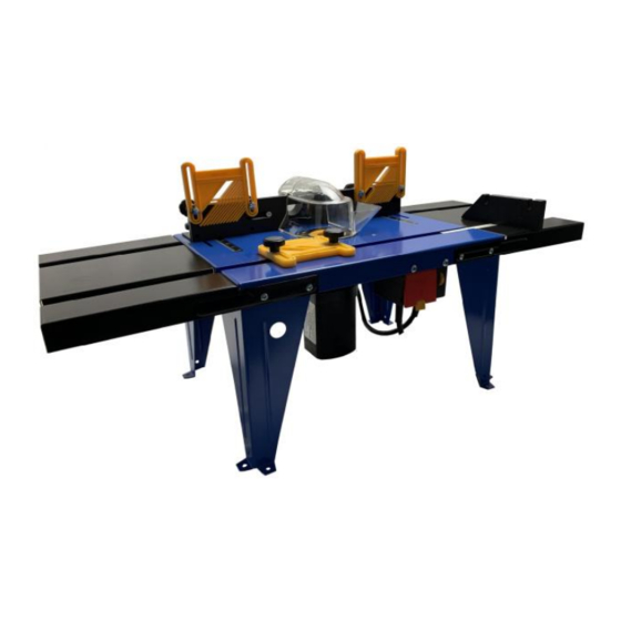
- Page 15 SAFETY GUARD #A FEATHER COMPONENTS MITRE GUIDE #B FEATHER FENCE COMPONENTS COMPONENTS MAIN TABLE WITH ROUTER EXTENSION TABLE SUPPORT STANDS SWITCH COMPONENTS...
Need help?
Do you have a question about the RT 150B and is the answer not in the manual?
Questions and answers
what routers fit the tri-hole mounting holes