Table of Contents
Advertisement
Quick Links
WARNINGS AND CAUTIONS
• WARNING: TO AVOID SERIOUS PERSONAL INJURY never push objects of any
kind into this product through openings, as they may touch dangerous voltages.
• WARNING: TO AVOID SERIOUS PERSONAL INJURY never touch uninsulated wires
or terminals unless the wiring has been disconnected at the network interface.
• Never install communications wiring or components during a lightning storm.
• Read and understand all instructions. Follow all warnings and instructions marked on
the product.
DESCRIPTION
The 95A03-1T Thermostat Display Control (TDC) is designed to be used with Leviton's
65A60-1 TDC Communication Interface and an Omnistat2 RC-2000 series thermostat as
an easy-to-access interface. Leviton's RC-2000 series thermostats can control both single
and multi-stage HVAC systems, and are available using either hardwired communication or
ZigBee
®
wireless.
The TDC can be flush mounted on a wall for a clean and attractive appearance. It can be
used to select the desired temperature, adjust fan and mode settings, and more. The TDC
has a built-in temperature sensor that can be averaged with up to 3 other TDC sensors and/
or the sensor in the RC-2000 thermostat. Temperature averaging ensures precise reading
and automation for comfort and enhanced energy efficiency.
Required Components:
• Model 65A60-1 TDC Communication Interface (provided)
• Omnistat2 RC-2000 series thermostat with firmware Version 1.05B or later (sold sepa-
rately)
INSTALLATION
Connect the TDC Communication Interface to the RC-2000 thermostat as follows – See
Figure 1:
UP
TDC Communication
3
(C)
Blue
2
1
Blue
(RC)
RC-2000
Figure 1 – Connecting the 65A60-1 to the RC-2000
1) Connect the green, yellow, and red wires on the TDC Communication Interface to the
Green, Yellow, and Red terminals under the section marked "Remote Sensor Module" on
the RC-2000.
2) Connect one of the blue wires on the TDC Communication Interface to Terminal 1 (RC)
on the RC-2000.
3) Connect the other blue wire on the TDC Communication Interface to Terminal 3 (C) on
the RC-2000.
4) Connect the TDC to the TDC Communication Interface, using Cat 5, unshielded, twisted
pair (UTP) for communications. Run the Cat-5 cable between the location of the TDC
and the location of the TDC Communications Interface (which is usually at the location of
the RC-2000 thermostat).
Each end of the wire is terminated with an RJ45 connector. The correct wiring scheme for
the Cat 5 cable is standard EIA/TIA 568A. Properly terminating the Cat 5 cable is crucial for
the operation of the system. The total distance of Cat 5 between the TDC and TDC Com-
munication Interface not exceed 1500 feet.
Insert the RJ45 connector on one end of the cable to the jack labeled U2 on the TDC Com-
munication Interface. Insert the RJ45 connector on the other end of the cable to the jack on
the TDC.
A maximum number of 4 TDC keypads can be connected to a TDC Communication Inter-
face.
CONFIGURING THE TDC
After the TDC and TDC Communication Interface have been installed and connected, there
are several installation settings on the RC-2000 thermostat that need to be configured.
Note: Some of the TDC installation settings are only displayed if the TDC and TDC
Communication Interface have been installed and are communicating with the RC-2000.
To access the Installation Settings on the RC-2000:
1. From the Home Page, press the Scroll Wheel.
2. Turn the Scroll Wheel until "Setup" is highlighted.
3. Press the Scroll Wheel or [Select] to select "Setup".
4. Turn the Scroll Wheel until "Installation Settings" is highlighted.
5. Press the Scroll Wheel or [Select] to select "Installation Settings".
6. Read the warning and then press [Continue] to proceed.
THERMOSTAT DISPLAY CONTROL (TDC) INSTALLATION KIT
Installation Instructions
UP
65A60-1
Inter face
THERMOSTAT
Cat. No. 95A03-TKT
INSTALLATION
WARNINGS AND CAUTIONS
• Do not use this product near water - e.g., near a tub, wash basin, kitchen sink or
laundry tub, in a wet basement, or near a swimming pool.
• Never install communications components in wet locations unless the components are
designed specifically for use in wet locations.
• Use caution when installing or modifying communications wiring or components.
• SAVE THESE INSTRUCTIONS.
Temperature Sensors
To configure the temperature sensor(s) that will be used to display the temperature on the
TDC:
1. From the Installation Settings menu, turn the Scroll Wheel until "Temperature Sensors" is
highlighted.
2. Press the Scroll Wheel or [Select] to select "Temperature Sensors".
The Temperature Sensor settings are used to configure the internal temperature sensor,
optional remote temperature sensor, and temperature sensor in the TDC. Any tempera-
ture sensors that are set as the same type (i.e. indoor or outdoor) will display the average
temperature reading among the sensors.
Internal Sensor:
External Sensor 1: This will enable the external temperature sensor for indoor or
External Sensor 2: This will enable the expansion module temperature sensor for
TDC Sensor:
Red
By default, the RC-2000 is configured to only display the temperature of its internal tem-
Yellow
Green
perature sensor on the TDC.
To average the internal sensor in the RC-2000 with the temperature sensor in the TDC, set
the Internal Sensor to "Enabled" and the TDC Sensor to "Indoor".
To use only the temperature sensor in the TDC, set the Internal Sensor to "Disabled" and
the TDC Sensor to "Indoor".
Communication
Jumper
Note: when multiple TDC keypads are connected to the TDC Communication Interface and
if the TDC Sensor is set to "Indoor", then all of the temperature of each of the temperature
sensors in the TDC keypads will be averaged together.
TDC Options
To configure the Periodic Flash and Eco Mode setback options for the TDC:
1. From the Installation Settings menu, turn the Scroll Wheel until "TDC Options" is high-
lighted.
2. Press the Scroll Wheel or [Select] to select "TDC Options".
Periodic Flash
When Periodic Flash is sent to "Off" (default setting), one minute after that last time a button
is pressed on the TDC keypad, the display on the TDC is turned off. The display will remain
off until a button is pressed on the TDC keypad. When a button is pressed on the TDC
keypad, the display is turned back on for one minute.
When Periodic Flash is set to "On", the TDC display is turned on and the temperature is
displayed every ten seconds. After displaying the temperature for three second, the display
is turned off for ten seconds. Whenever a button is pressed on the TDC keypad, the display
is turned on for one minute.
Eco Mode Setback
Eco Mode is used to quickly setback the heat and cool setting of the RC-2000 thermostat
for energy savings. The TDC can be used to set the RC-2000 to Eco Mode when leaving
the premises, and then restored to normal upon returning.
The number set for the Eco Mode Setback option is the number of degrees that the heat
and cool setting will be setback whenever the TDC is set to Eco Mode. The default setting
is 4 degrees.
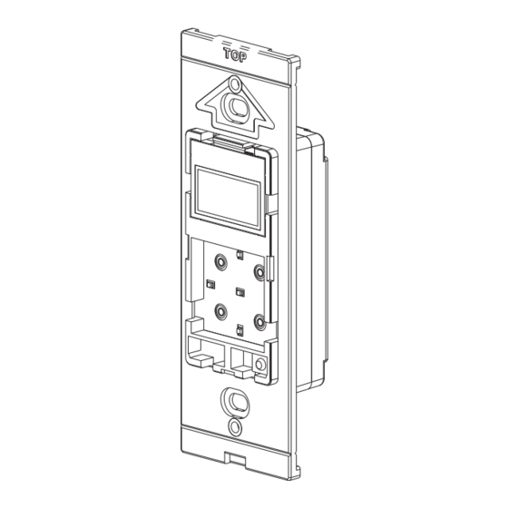
CHANGING THE COLOR OF THE TDC
The color of the TDC may be changed to complement the interior décor. The TDC is sup-
plied with a white faceplate, rubber keypad, and insert. Additional colors are available; con-
tact your Leviton distributor for more information. Change the color of the TDC as follows:
1. Remove the faceplate.
2. The insert attaches to the TDC with two latches on the right and two on the left. Using a
small-blade screwdriver, gently depress each latch on one side while lifting up on the insert.
Once the latches are released on one side, remove the insert from the other side.
3. Remove the rubber keypad.
4. Insert the new rubber keypad. Align the latches of the new insert to the openings on the
TDC and gently snap into place.
5. Attach the new faceplate.
DI-020-95A03-05A
This will enable or disable the onboard temperature sensor for
indoor use only. *Enabled
outdoor use. All indoor and outdoor temperatures are averaged
between all sensors of the same type. *Disabled
indoor or outdoor use. All indoor and outdoor temperatures are
averaged between all sensors of the same type. *Disabled
This will enable the expansion module temperature sensor for
indoor or outdoor use. All indoor and outdoor temperatures are
averaged between all sensors of the same type. * Disabled
(95I03-TKT)
AR3363
ENGLISH
Advertisement
Table of Contents

Related Manuals for Leviton 95A03-TKT

Summary of Contents for Leviton 95A03-TKT
- Page 1 Additional colors are available; con- Communication Interface have been installed and are communicating with the RC-2000. tact your Leviton distributor for more information. Change the color of the TDC as follows: To access the Installation Settings on the RC-2000: 1.
- Page 2 Leviton’s option, of Product that fails due to defect in material or workmanship. Leviton reserves the right to replace product under this Limited Warranty with new or remanufactured product. Leviton will not be responsible for labor costs of removal or reinstallation of Product. The repaired or replaced product is then warranted under the terms of this Limited Warranty for the remainder of the Limited Warranty time period or ninety (90) days, whichever is longer.
Need help?
Do you have a question about the 95A03-TKT and is the answer not in the manual?
Questions and answers