Advertisement

Quick Links

1
SERVICE MANUAL
Level 1&2
RM-647
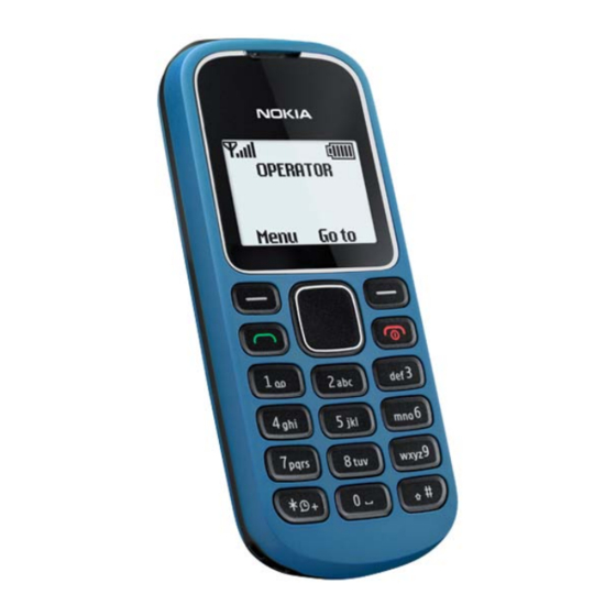
Transceiver characteristics
Band:
EGSM 900/1800
Display:
1.36" black and white display
96 x 68 pixels resolution
Operating System:
S30
Connections:
Cellular radio: GSM
2.0 mm DC charger connector
3.5mm AV connector
Talk time
GSM:
Up to 12.78 hours
Note: Talk times are dependant on network
parameter settings.
Confidential • Copyright © 2010 NOKIA • All rights reserved
Nokia 1282
Service Manual Level 1&2
Standby
GSM:
Up to 720 hours
Version 1.0
RM-647
ISSUE 1

Advertisement

Table of Contents
loading

Summary of Contents for Nokia 1282

  • Page 1 3.5mm AV connector • Talk time Standby GSM: GSM: Up to 12.78 hours Up to 720 hours Note: Talk times are dependant on network parameter settings. Confidential • Copyright © 2010 NOKIA • All rights reserved Version 1.0 ISSUE 1...
  • Page 2: Table Of Contents

    Battery information ................................. 8 Exploded view ................................... 9 Service devices ..................................10 SW-update ....................................11 Disassembly instructions ..............................12 Assembly hints ..................................17 Solder components ................................18 Confidential • Copyright © 2010 NOKIA • All rights reserved Version 1.0 ISSUE 1...
  • Page 3: Change History

    30.08.2010 First approved version The purpose of this document is to help NOKIA service levels 1 and 2 workshop technicians to carry out service to NOKIA products. This Service Manual is to be used only by authorized NOKIA service suppliers, and the content of it is confidential. Please note that NOKIA provides also other guidance documents (e.g.
  • Page 4: Copyright

    Nokia operates a policy of continuous development. Nokia reserves the right to make changes and improvements to any of the products described in this document without prior notice. Under no circumstances shall Nokia be responsible for any loss of data or income or any special, incidental, consequential or indirect damages howsoever caused.
  • Page 5: Warnings And Cautions

    3. Use only approved components as specified in the parts list. 4. Ensure all components, modules screws and insulators are correctly re–fitted after servicing and alignment. 5. Ensure all cables and wires are repositioned correctly Confidential • Copyright © 2010 NOKIA • All rights reserved Version 1.0 ISSUE 1...
  • Page 6: Esd Protection

    RM-647 Service Manual Level 1&2 3. ESD PROTECTION Nokia requires that service points have sufficient ESD protection (against static electricity) when servicing the phone. Any product of which the covers are removed must be handled with ESD protection. The SIM card can be replaced without ESD protection if the product is otherwise ready for use.
  • Page 7: Care And Maintenance

    All of the above suggestions apply equally to the product, battery, charger or any accessory. Confidential • Copyright © 2010 NOKIA • All rights reserved Version 1.0 ISSUE 1...
  • Page 8: Battery Information

    Batteries’ performance is particularly limited in temperatures well below freezing. Do not dispose batteries in a fire! Dispose of batteries according to local regulations (e.g. recycling). Do not dispose as household waste. Confidential • Copyright © 2010 NOKIA • All rights reserved Version 1.0 ISSUE 1...
  • Page 9: Exploded View

    I0010 DC JACK D-COVER I0011 I0012 TYPE LABEL I0009 BATTERY COVER I0013 Only available as These parts can not be Ver. 1.0 assembly reused after removal Confidential • Copyright © 2010 NOKIA • All rights reserved Version 1.0 ISSUE 1...
  • Page 10: Service Devices

    SF-204 Flash adapter found in “Recommended service equipment” document on NOKIA Note that the switch must be set Online. to Normal mode! Confidential • Copyright © 2010 NOKIA • All rights reserved Version 1.0 ISSUE 1...
  • Page 11: Sw-Update

    Service Manual Level 1&2 8. SW-UPDATE Flash concept - (Point of Sales) Please check always for the latest version of flash software, wich is available on Nokia Online. Confidential • Copyright © 2010 NOKIA • All rights reserved Version 1.0...
  • Page 12: Disassembly Instructions

    6) Then release the left side of the A-COVER by of the A-COVER. The SS-93 can be used to support sliding finger between the A-COVER and the D- the releasing procedure. COVER. Confidential • Copyright © 2010 NOKIA • All rights reserved Version 1.0 ISSUE 1...
  • Page 13 11) The KEYMAT and the A-COVER can be separated. 12) Unscrew the six TORX+ size 4 screws in the order shown. Remove them with the tweezers. Do not use them again. Discard them. Confidential • Copyright © 2010 NOKIA • All rights reserved Version 1.0 ISSUE 1...
  • Page 14 D-COVER. 17) The ENGINE BOARD/UI SHIELDING can be 18) Release the four shown clips with the SS-93, to separated from the D-COVER. release the UI SHIELDING. Confidential • Copyright © 2010 NOKIA • All rights reserved Version 1.0 ISSUE 1...
  • Page 15 22) Remove the DC JACK with the tweezers. 23) Lever out the SPEAKER with the sharp end of the 24) Remove the SPEAKER with the tweezers. SS-93. Confidential • Copyright © 2010 NOKIA • All rights reserved Version 1.0 ISSUE 1...
  • Page 16 Nokia 1282 RM-647 Service Manual Level 1&2 -END OF DISASSEMBLY- 25) Nokia 1282 disassembly is now complete. Confidential • Copyright © 2010 NOKIA • All rights reserved Version 1.0 ISSUE 1...
  • Page 17: Assembly Hints

    Service Manual Level 1&2 10. ASSEMBLY HINTS 1) Tighten the four TORX + size 4 screws to the torque of 15 Ncm in the order shown. Confidential • Copyright © 2010 NOKIA • All rights reserved Version 1.0 ISSUE 1...
  • Page 18: Solder Components

    Nokia 1282 RM-647 Service Manual Level 1&2 11. SOLDER COMPONENTS No Level 1 and 2 soldering work for Nokia 1282 Confidential • Copyright © 2010 NOKIA • All rights reserved Version 1.0 ISSUE 1...

This manual is also suitable for:

Rm-647

Table of Contents