Advertisement
Quick Links
Advertisement

Related Manuals for Fiberplex FOI-5601

Summary of Contents for Fiberplex FOI-5601
- Page 1 USER MANUAL E1 Fiber Transceiver FOI-5601 / TD-5601...
- Page 3 Ambient Temperature Units and systems by FiberPlex are generally designed for an ambient temperature range (i.e. temperature of the incoming air) of 5 °C to 40 °C (41 °F to 104 °F). When rack mounting the units, the following facts must be considered: •...
- Page 4 The information in this document has been carefully checked and is believed to be accurate at the time of publication. However, no liability is assumed by FiberPlex for inaccuracies, errors, or omissions, nor for loss or damage resulting either directly or indirectly from use of the information contained herein.
-
Page 5: Getting Started
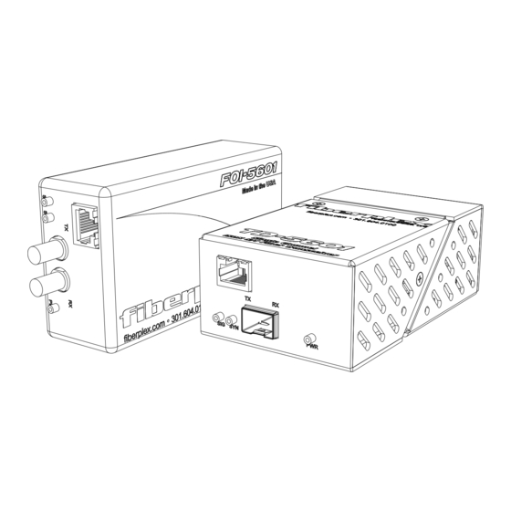
2km, while singlemode optics can further extend the distance to 20km. A typical link consists of two FOI-5601, one at each end of the network, with a duplex fiber optic cable between them. Differences between FOI-5601 and TD-5601 Functionally, the FOI-5601 and TD-5601 are identical. - Page 6 Front Indicators/Connections Figure 1 TD-5601 (left), FOI-5601 (middle), and FOI-5601 with ST connectors (Right) Front Face RJ-45 Port – Used to connect your copper ISDN S/T line to the TD/FOI-5601. This port accepts a standard RJ-45 male connector. Pinout Signal SFP Port –...
- Page 7 Figure 2 TD-5601 (left) and FOI-5601 (right) Rear Face Circular DC Power Connection – DC power entry for the unit. On the FOI-5601 this is a Lemo connector designed to interface with either a PSQ power module or RMC chassis. On the TD-5601 this is a standard DC connection for use with the included DC wall power supply.
- Page 8 Flexible mounting allows the FOI-5601 to be chassis mounted or standalone configuration. Any combination of 8 FiberPlex FOI units can be mounted in a RMC-3101 using CMA-3002 chassis mount adapters. The RMC-3101 can accommodate hot swapped redundant power. Alternately, the FOI-5601 can be used in a standalone application when paired with a PSQ-4909 for full range AC operation or the PSQ-4920 for 12-48VDC operation.
- Page 9 Figure 5 TD Module Installation on a TDR-01 Tray Figure 6 FOI unit Installed in an RMC-3101 Chassis...
- Page 10 Identify the Latch Type of the SFP Module SFP Modules have various latching mechanisms to secure them into the SFP Cage of a device. FiberPlex fiber optic products can support a host of manufacturers and brands of SFP Modules, so the user may encounter any number of different latches.
- Page 11 Inserting a SFP Module Attach an ESD-preventative wrist or ankle strap, following its instructions for use. Disconnect and remove all interface cables from SFP Module. If the SFP Module has a Bail Clasp, close the Bail Clasp before inserting the SFP Module. With the gold finger connector on the bottom and the label on the top, line up the SFP Module with the empty cage and slide it in making sure that it is completely inserted and seated in the cage.
-
Page 12: Specifications
Specifications Figure 7 FOI-5601 Dimensions Figure 8 TD-5601 Dimensions... -
Page 13: Other Considerations
SFP MSA (SFF-8431, SFF-8432, SFF-8433) compliant slot, data rate 266 – 1.25 Gbps PHYSICAL SPECIFICATIONS Case Dimensions Length Width Height Weight FOI-5601 (Size 4) 4.5 in (114 mm) 1.453 in (37 mm) 2.56 in (65 mm) 2 lb (0.9 kg) TD-5601 4.5 in (114 mm) 2.75 in (70 mm) - Page 14 NOTES...
- Page 16 18040-412 Guilford Rd. • Annapolis Junction, MD 20701 fiberplex.com • clients@fiberplex.com • 301.604.0100 UM5601-1712...
Need help?
Do you have a question about the FOI-5601 and is the answer not in the manual?
Questions and answers