RFX MIDIBUDDY MP128 - Midi Controller Manual
- Owner's manual (2 pages) ,
- Owner's manual (2 pages)
Advertisement
SPECIFICATIONS
| Size: | 17" X 5" X 1.5" (381 x 127 x 38 mm) |
| Weight: | 3 lbs. (1.4 kg) |
| Power: | 7 - 15 VAC/VDC 80 mA |
| Phantom Power: | 7 - 25 VDC 80 mA, pin 1 neg, pin 3 pos. |
| Display: | 2 digit red, .56" high efficiency |
| Output: | Standard MIDI Program Change, Song Start/Stop |
| Output Jacks: | 2 DIN jacks (MIDI OUT, MIDI SHARE) |
| Chassis: | Black painted steel |
INTRODUCTION
Thank you for purchasing the RFX MP128 MIDIBUDDY. The MP128 sends standard MIDI program changes to select patches on a MIDI keyboard, digital signal processor, or other MIDI controllable device.
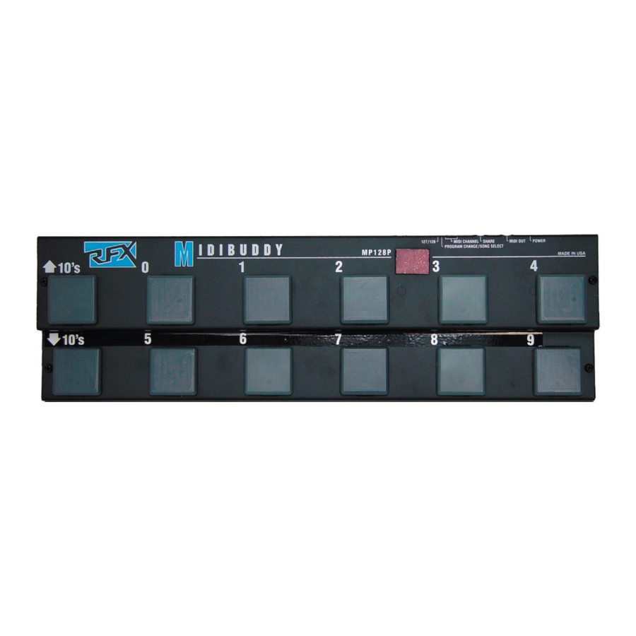
DESCRIPTION

- Program Select, Function buttons
- Program/Function Display Window
- 127/128 (Dip switch #6) Switch
- PROGRAM CHANGE/SONG SELECT (DIP switch # 5) Switch
- MIDI CHANNEL SELECT Switches (DIP switches 4,3,2, and 1)
- SHARE output
- MIDI output jack
- POWER jack
INSTALLATION
- Apply power (Rolls Model PS27, 12VDC, 150mA) to the Power jack on the rear of the MP128. The MP128 may also be "phantom-powered" which means powering the unit via unused pins of the MIDI cable. See the back page of this manual for more on MIDI phantom power.
- Connect the MIDI OUT of the MP128 using a standard MIDI cable, to the MIDI IN on the device to be controlled. The MIDIBUDDY may be used on the floor and foot switched or placed on top of a keyboard for easy hand access. The unit, with slight modification, will fit in a standard 19 inch audio rack if necessary.
- The "SHARE" jack is in parallel with the OUT jack and operates as a MIDI "Thru" for connecting several devices together. For example, two MP128s operating on different MIDI channels could use the same MIDI path.
OPERATION
The MP128 follows MIDI standard protocol, and will change programs on any MIDI controllable device. The controlled device and the MP128 must be on the same MIDI channel (see chart - next page), or the device should be on an "omni" channel.
The unit sends up to ten different program changes, in twelves different banks. Bank 0 sends program changes 1 - 9 (there is no program change 0), bank 1 sends program changes 10 - 19, bank 2 sends program changes 20 - 29, etc. The LED display on the MIDIBUDDY shows the MIDI program number (0 - 127, or 1 - 128 depending on the setting of DIP switch # 6).
As the 10s Up or Down are scrolled through, the unit increments or decrements through banks 0 through 120. The ones digit is selected by switches 0 - 9. MIDI data is sent only when a 1 - 9 button is selected except as described below. The display will show a "-" in the right hand digit when no MIDI information is sent, or when a 10's UP or DOWN button is pressed.
For example; to send program 47, press the 10s UP or 10s DOWN until the display reads "4-" then press the 7 button. When the 7 button is pressed, program 47 is sent out and the number is displayed by the LED readout.
MIDI Start and Stop Commands
When program "00" is selected, the MP128 display shows an "ST" (which looks more like an Sr), and sends a MIDI start command. This may be used to start a MIDI sequencer. When program "129" is selected, an "SP" is displayed and a MIDI Stop command is sent.
Setting the DIP Switches
 NOTE: DISCONNECT THE POWER CABLE TO MAKE DIP SWITCH CHANGES. SETTINGS TAKE EFFECT UPON POWER-UP.
The MIDI Channel is set with DIP switches 1 - 4 on the rear of the MP128. If all switches are in the off position, MIDI channel 1 is selected, if all are on, MIDI channel 16 is selected. Use the following chart to select the MIDI Channel.
| CH# | ON | OFF | CH# | ON | OFF |
| 1 | 1,2,3,4 | 9 | 4 | 1,2,3 | |
| 2 | 1 | 2,3,4 | 10 | 1,4 | 2,3 |
| 3 | 2 | 1,3,4 | 11 | 2,4 | 1,3 |
| 4 | 1,2 | 3,4 | 12 | 1,2,4 | 3 |
| 5 | 3 | 1,2,4 | 13 | 3,4 | 1,2 |
| 6 | 1,3 | 2,4 | 14 | 1,3,4 | 2 |
| 7 | 2,3 | 1,4 | 15 | 2,3,4 | 1 |
| 8 | 1,2,3 | 4 | 16 | 1,2,3,4 |
- Switch #5 selects whether the MP128 transmits Program Change information only, or transmits Program Change and Song Pointer.
- Since some MIDI devices display their programs as 0 - 127, and others display 1 - 128, the MIDIBUDDY's DIP switch #6 will select either of these two. If switch #6 is in the off (up) position, the MP128 will display program numbers 0 - 127. If switch #6 is on (down), the MP128 will display program numbers 1 - 128 (which is the way the MP128 comes from the factory).
RFX MIDI PHANTOM POWER

Inspired by an article in the December 1989 issue of Electronic Musician (by Craig Anderton), we decided to emulate their MIDI phantom power model for RFX equipment. MIDI receivers supply 12 VDC on pins 1 and 3, and transmitters receive power on those same pins. Many MIDI devices can be modified to supply power down the cable, but of course RFX makes no warranty to anyone as to the applicability of this modification or any damage that might be done as a result thereof. We supply this note for those adventurous people who may want to give it a try.
Connect pin 1 to circuit ground, and pin 3 to +9 - +15 VDC of the receiving unit.

Documents / ResourcesDownload manual
Here you can download full pdf version of manual, it may contain additional safety instructions, warranty information, FCC rules, etc.
Advertisement


Need help?
Do you have a question about the MIDIBUDDY MP128 and is the answer not in the manual?
Questions and answers