Summary of Contents for Apex Digital SGS
- Page 1 Solar Geyser System (SGS) TECHNICAL MANUAL Document Number: SGSP100 20 February 2023...
-
Page 2: Table Of Contents
Local Requirements 3.12 Other Considerations 4. Device Description Overview And Description Electrical Interfaces 4.3 Identification 5. Installation Safety Installation Of The SGS Electrical Installation Powering Up The SGS 6. Operation Commissioning Operating Modes 6.3 Default Settings LED Status Indicators Fault Finding... -
Page 3: Introduction
• Unaffected by load-shedding and grid outages. • 1 x pair MC4 connectors 1.2 DEVICE DOCUMENTATION The Apex SGS is the heart of a water heating system – Apex SGS documentation includes this manual and its intelligently heating water in a standard electric geyser datasheet sheet. -
Page 4: Technical Specifications
Solar Geyser System 2. TECHNICAL SPECIFICATIONS ELECTRICAL SPECIFICATIONS: Description Specification Voltage 230V AC Frequency 50 Hz AC Input: Current Connection 3 x 4mm Screw Terminals Installation Pre-requisites AC MCB and local Isolation point (not supplied) AC Detection Voltage 230V AC AC Mode Output: Frequency 50 Hz Current Input Voltage Range 110 - 230VDC Maximum Input Current... - Page 5 Solar Geyser System Description Specification Dimensions (Length X Breadth X Depth) 210mm x 225mm x 84mm Cooling Natural Convection Mechanical specifications: Cable Strain Relief Integrated for AC cables and thermal probe IP2X Ingress Protection Terminal Access Removable cover Mounting Vertical only Installation Environment Indoor Use only. Not for in-roof installation. specifications: Wall plugs with pozi screws Fasteners...
-
Page 6: Safety Instructions
Immediately after receiving the package, make sure that the packaging and the device have no signs of damage. If the packaging shows any sign of damage or impact, damage of the SGS should be suspected and it should not be installed. -
Page 7: Installation Place
Any person in charge of the installation, commissioning, To ensure safe use, the Apex SGS must only be used in maintenance, or replacement of a Apex SGS must first compliance with the instructions in this manual. read and understand this user manual, especially the Legal and safety regulations must also be adhered to, safety recommendations and shall be trained to do so. -
Page 8: Device Description
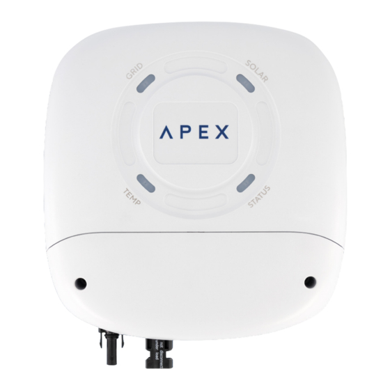
4. DEVICE DESCRIPTION 4.1 OVERVIEW AND DESCRIPTION FRONT: Figure 2 shows the front of the Apex SGS which has the following features: The SGS’s front fascia consists of 4 state indicating multicolour LEDs. Below the LEDs is the cover over the terminal chamber where all the cables terminate, which is secured with 2 Philips head screws. -
Page 9: Installation
Attach the SGS to its bracket by positioning it over the hooks and sliding it downwards. There should be a small gap between the bracket and the rear surface of the SGS’s Figure 3. SGS Electrical Installation Overview housing to allow for sufficient air flow. The SGS shall be installed with all the relevant electrical 5.2 INSTALLATION OF THE SGS... - Page 10 Connect a supply from a suitably sized dedicated circuit breaker in the distribution board with a suitable cross section cable to the SGS. This cable is the power supply to the SGS and is terminated at the “L”, “N” and earth (AC INPUT) terminals on the PC board. Ensure that the Live,...
-
Page 11: Powering Up The Sgs
Installing the collar is an easy process. Start at the geyser and work towards the SGS. With the power to the geyser switched off, remove the standard geyser thermostat and feed the copper strip into the thermostat pocket, all the way up to the collar. -
Page 12: Operation
6.1 COMMISSIONING 6.3 DEFAULT SETTINGS The SGS is designed to assume temperature control The SGS can work directly out of the box with no further of the geyser to which it is connected and operates settings or internet connection. autonomously. However, the original thermal cut-out... -
Page 13: Led Status Indicators
Error Wi-Fi connected 6.5 FAULT FINDING If the SGS does not work correctly or displays a fault is present with the Status LED, it is necessary to correct an abnormal occurrence. All error status messages are available in the User App. Once an error is corrected, reset the fault by turning off / on both PV and AC together. The following table shows monitored faults which can occur and possible solutions:... -
Page 14: Other Errors
Apex. Fuses: To request support or an RMA number please go to The Apex SGS has 2 fuses inside, 1 each for the AC and DC www.ApexSolar.Tech supplies. Should either supply fail to correctly power up the unit, check these 2 fuses on the main board. -
Page 15: Mobile Applications & Wifi Connectivity
7.2 CONNECTIVITY app. The process for this varies from browser to browser, A new Apex SGS will start up with its own Wi-Fi hotspot but the general idea is the same. Here are the instructions active and this is indicated by the Status LED on the SGS for popular web browsers. -
Page 16: Installers Remote Monitoring
7.2.1 WEB APP AND REMOTE ACCESS 7.3.1 ENROLLING A DEVICE The Apex SGS needs to be connected to a local Wi-Fi Once the installers account has been created, the installer network with internet access for the Web App to work. -
Page 17: User's Remote Monitoring
The Function View is where you can interact with your Apex SGS. Boost The Apex SGS will heat the water to the Boost setpoint in the shortest possible time, which will use AC power. Tap again to deactivate Boost. Menu: Geyser Activity... -
Page 18: Contact Us
8. Contact us For more or updated information, new products and technical support please visit: www.ApexSolar.Tech Solar Geyser System Manual...


Need help?
Do you have a question about the SGS and is the answer not in the manual?
Questions and answers