
Summary of Contents for Total Source 161TA6945
- Page 1 Original operating manual OPERATING MANUAL SOLID TYRE PRESS 161TA 694 5 – 161TA 694 4 08/2021 – V01...
- Page 2 © 08-2021. TVH and TotalSource are registered trademarks. TVH Parts Holding NV, Brabantstraat 15, B-8790 Waregem. All rights reserved. ® ® No part of this publication may be reproduced or communicated in any form or by any means, electronic or mechanical, including copying, recording or use in an information storage or retrieval system, without prior and explicit permission of TVH Parts Holding NV.
- Page 3 Bulgarian Можете да намерите това ръководство на Вашия език чрез линка, посочен по – долу. Czech Tento návod najdete ve svém jazyce prostřednictvím odkazu níže. Danish Du kan finde denne vejledning på dit sprog via nedenstående link. German Sie finden diese Bedienungsanleitung in Ihrer Sprache unter folgendem Link. Greek Μπορείτε...
- Page 4 Thank you for using our product. For your safety and to ensure a correct operation, we would like to bring to your attention some aspects of this manual: • This booklet supplies useful instructions for the correct operation and maintenance of the product.
-
Page 5: Table Of Contents
TABLE OF CONTENTS INTRODUCTION ..................DESCRIPTION . -
Page 6: Introduction
INTRODUCTION This manual contains all the necessary information on the installation and operation of the solid tyre press. Some of the maintenance operations should only be carried out by professional technicians. If you require this information and the maintenance steps, please contact your dealer. Also included in this manual are a number of safety instructions to create a safe working environment. - Page 7 This solid tyre press may be unsafe if adequate maintenance is neglected. Therefore, adequate maintenance facilities, trained personnel and procedures should be provided. Maintenance and inspection shall be performed in conformity with the following practices: 1. A scheduled planned maintenance, lubrication and inspection system should be followed (see maintenance instructions chapter 8).
-
Page 8: Description
DESCRIPTION 2.1. Technical data Always check the type plate for the correct information. 161TA6945 Type TP120 Capacity (kg) 120 000 Max tyre dimension (mm) 1000 x 20 Total length (mm) 2080 Total width (mm) Total height (mm) 2151 Operating pressure (bar) Cylinder stroke (mm) - Page 9 1200 2080 9/68...
-
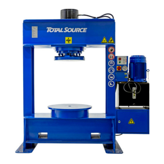
Page 10: Main Components Of The Product
2.2. Main components of the product N° Component N° Component Cylinder Safety decals Hydraulic hoses Electric motor Control panel 10 Mounting holes ON/OFF button 11 Fork pockets Pressure gauge 12 Pressure plate Hydraulic pump unit 13 Type plate Electrical equipment box 2.3. -
Page 11: Type Plate
2.4. Type plate N° Explanation Brabantstraat 15 • BE- 8790 Waregem T +32 56 43 42 11 • F +32 56 43 44 88 T +32 56 43 42 11 • F +32 56 43 44 88 Address info@totalsource.com • www.totalsource.com CE marking Brand TYPE... -
Page 12: Safety Instructions
SAFETY INSTRUCTIONS 3.1. Explanation of the safety decals If the decals are damaged or missing, please replace them. N° Decal Explanation Reference Type plate 166TA6950 Brabantstraat 15 • BE- 8790 Waregem T +32 56 43 42 11 • F +32 56 43 44 88 info@totalsource.com •... -
Page 13: Electrical Diagram And Hydraulic Diagram
N° Decal Explanation Reference Hearing protection mandatory 162TA5381 Safety gloves mandatory 162TA1674 Safety shoes mandatory 123TA5144 Risk of electric shock 166TA6677 Brand 166TA2311 Read the manual before each use 166TA6675 Risk of entrapment in moving parts 126TA9774 3.2. Electrical diagram and hydraulic diagram Electrical and hydraulic diagrams are available on request. -
Page 14: General Safety Instructions
3.3. General safety instructions • Do not operate the product unless you are of age. • The person responsible for the use of the product must make sure that all of the safety rules in force in the country of its use are applied, to guarantee that the equipment is used in conformity with the use for which it is destined and to avoid any dangerous situation for the user. -
Page 15: Transport And Storage
TRANSPORT AND STORAGE The operator should wear safety glasses, hearing protection, safety shoes and safety gloves when using or maintaining the solid tyre press. • If lifting equipment is used when installing the solid tyre press, the operators must also be familiar with the operating procedures of the lifting equipment used. Read the manual before using the lifting equipment. - Page 16 1. Lifting 1. Make sure the solid tyre press is on a flat and stable surface. 2. Stand in front of the solid tyre press with the forklift. 3. Place the forks at the same height as the fork pockets. 4.
-
Page 17: Storage
2. Lowering 1. When lowering the solid tyre press, first return the mast of the forklift to its upright position. Do this gently and slowly so that the solid tyre press cannot tip over. 2. Lower the forks until the solid tyre press is on the ground again 4.2. -
Page 18: Assembly And Installation
161TA6944 Description Amount Reference Solid tyre press 161TA6944 Reduction table 166TA5332 Operating manual 166TA9027 161TA6945 Description Amount Reference Solid tyre press 161TA6945 Reduction table 166TA5332 Operating manual 166TA9027 The necessary tools to assemble and disassemble tyres are not supplied with the solid tyre press. -
Page 19: Required Materials For Assembly
5.3. Required materials for assembly See diagram below for dimensions • 8 wedge bolts • 8 expansion plugs • Drilling machine • Drill bit • Power impact tool Wedge bolt Expansion plug Hole Spec Length Outer diameter Length Diameter Depth 5.4. Place designation of the product A newly delivered solid tyre press or a solid tyre press on which a new accessory has been fitted must not be installed or put into operation until all transport securing devices and packaging have been removed and the machine has been thoroughly inspected. -
Page 20: Securing The Product To The Ground
5.5. Securing the product to the ground 1. Place the machine on the ground. When doing so, leave the forks temporarily in place. 2. Using a pencil, mark the spots on the ground where you are going to drill by marking the drill holes. -
Page 21: Commissioning
Attach a plug to the power cable because the solid tyre press cannot be directly connected to the power supply. 2. If you are working with solid tyre press 161TA6945, the solid tyre press must be connected to a 3 x 380-volt power supply. If you are working with 161TA6944, the solid tyre press must be connected to a 3 x 220-volt power supply. -
Page 22: The Emergency Stop Switch
If the motor turns in the other direction, contact the technician. Phase L1 and phase L2 must be swapped. 5. Activate the cylinder by pressing the DOWN button briefly. 6. Return the cylinder to its original starting position by pressing the UP button. 7. -
Page 23: Operation
OPERATION 7.1. Safety instructions for operating the product • A damaged or malfunctioning machine must never be used. If damage or malfunctions are discovered during pre-operation inspection or function tests, the machine must be tagged and removed from service. • The operator should wear safety glasses, hearing protection, safety shoes and safety gloves when using or maintaining the solid tyre press. - Page 24 2. Operating the solid tyre press 1. Insert the plug of the solid tyre press into the wall socket. 2. Switch on the power with the main switch. 3. Press and hold the START button to switch on the electric motor. As soon as the oil pump starts working, the green light will illuminate.
- Page 25 Tyre size Rim size Cage number Flange ring Pressure ring 15 x 4.5 x 8 3.00 x 8 8” (203 mm) 8” (203 mm) 500 x 8 3.00 x 8 8” (203 mm) 8” (203 mm) 18 x 7 x 8 4.33 x 8 8”...
- Page 26 5. Use plenty of tyre grease on the rim. 6. Use plenty of tyre grease on the inside of the tyre. 7. Place the tyre on the rim with two people. 8. Place the tyre press cage on the tyre. It is extremely important that all parts are placed perpendicular to each other.
- Page 27 12. Remove the cone but leave the cage. 13. Place the advance band. 14. Press down further to create the needed space. 15. Fit the advance band. 16. Press the UP button to release pressure. 17. Position the side ring on top of the advance band. 18.
- Page 28 B. Press-on tyres 1. Centre the specific tool. 2. Place the plate on the tube. 3. Place the rim on the plate. 4. Use plenty of tyre grease on the rim. 5. Use plenty of tyre grease on the inside of the tyre. 6.
- Page 29 C. Clip solid tyres 1. Select the cage and, in the case of a standard tyre, a support plate of the correct size. 2. Place the support plate in the centre of the solid tyre press. 3. Place the rim on the support plate. 4.
- Page 30 It is extremely important that all parts are placed perpendicular to each other. 9. Press the DOWN button to lower the flange plate. 10. Press the UP button to release the pressure. Make sure the flange plate is in its starting position. 11.
- Page 31 5. Once the top of the rim is detached from the tyre, press the UP button to bring the flange plate back up. 6. Remove the side ring with a hammer. 7. Remove the locking ring using a crowbar and hammer. 8.
- Page 32 18. Place the extra tool on the cone. 19. Press the DOWN button. 20. Press out the rim. 21. Press the UP button to release the pressure. Make sure the flange plate is in its starting position. 22. Remove everything on the solid tyre press piece by piece. B.
- Page 33 7. The new tyre pushes the old tyre off the rim. 8. As soon as the old tyre drops down, the new tyre is correctly mounted on the rim. 9. Press the UP button to release the pressure. Make sure the flange plate is in its starting position.
- Page 34 C. Clip solid tyres 1. Place the support plate in the centre of the solid tyre press. 2. Place the tyre in the centre of the support plate. 3. Press the DOWN button to release the tyre from the rim. 4.
- Page 35 11. Press the DOWN button to push the rim out of the tyre. 12. Press the UP button to release the pressure. Make sure the flange plate is in its starting position. Is the above information still not clear? Go to our website www.tvh.com/downloads/movies and find the video of the solid tyre press.
-
Page 36: Maintenance
MAINTENANCE 8.1. Safety instructions for the repair of the product • Some of the maintenance operations should only be carried out by professional technicians. If you require this information and the maintenance steps, please contact your dealer. • Make sure you read the operating manual before carrying out maintenance. •... -
Page 37: Maintenance Schedule
8.2. Maintenance schedule Task 1. Daily maintenance check 2. Cleaning 3. Check of electrical wiring 4. Check of hydraulic lines 5. Check of the hydraulic oil level 6. Inspection of identification lights 7. Check of the fuses ... - Page 38 4. Check of hydraulic lines Check the hydraulic hoses for cracks, fissures or other weathering. In addition, check that the hose clamps are still tight and that no oil is leaking. If you notice that one or more hoses are weathered or broken, replace them immediately. Use only original spare parts or spare parts of equal quality.
- Page 39 9. Check for hydraulic oil leaks Check that no hydraulic hoses are leaking oil. Also check the ground for the formation of puddles of hydraulic oil. If you notice an oil leak, repair and replace the parts before continuing to use the device. Check can be done by the user.
-
Page 40: Troubleshooting
TROUBLESHOOTING N° Problem Cause Action The same fuse This may indicate a more complex Contact the service and repair keeps blowing problem in the electric motor department The device The floor is not level Move the appliance to a place where wobbles/stands the floor is level loose when I am... - Page 41 N° Problem Cause Action 10 I see smoke and/or Immediately switch off the entire smell something device at the mains and contact the burnt service and repair department 11 There is a fire Immediately switch off the entire device at the mains. Take the nearest extinguisher and try to extinguish the fire.
-
Page 42: Final Decommissioning And Disposal
FINAL DECOMMISSIONING AND DISPOSAL Final, proper decommissioning or disposal of the product must be performed in accordance with the regulations of the country in which the product is used. In particular, regulations governing the disposal of batteries, fuels and electronic and electrical systems must be observed. - Page 43 43/68...
-
Page 44: Annexes
Mounting of full tyres / Montage von Vollreifen / Montaje de Função neumáticos completos / Montaggio di pneumatici completi / Prensa para pneus cheios Merk / Marque / Brand / Marke / Total Source Marca Type / Typ / Tipo TP120 Model/ Modèle/ Modell/ Modelo TVH/26501814 •... - Page 45 ● dat de BANDENPERS VOOR VOLLE BANDEN voldoet aan alle toepasselijke bepalingen van de hierna vermelde richtlijnen en geharmoniseerde normen; que la PRESSE POUR PNEUS PLEINS satisfait à l’ensemble des dispositions pertinentes des directives et normes harmonisées ci-dessous; that the SOLID TYRE PRESS fulfills all the relevant provisions of the directives and harmonized standards stated herein below;...
- Page 46 Mounting of full tyres / Montage von Vollreifen / Montaje de Função neumáticos completos / Montaggio di pneumatici completi / Prensa para pneus cheios Merk / Marque / Brand / Marke / Total Source Marca Type / Typ / Tipo TP120 Model/ Modèle/ Modell/ Modelo TVH/26501830 •...
- Page 47 ● dat de BANDENPERS VOOR VOLLE BANDEN voldoet aan alle toepasselijke bepalingen van de hierna vermelde richtlijnen en geharmoniseerde normen; que la PRESSE POUR PNEUS PLEINS satisfait à l’ensemble des dispositions pertinentes des directives et normes harmonisées ci-dessous; that the SOLID TYRE PRESS fulfills all the relevant provisions of the directives and harmonized standards stated herein below;...
-
Page 48: 11.2. Spare Parts List Tyre Press
11.2. Spare parts list tyre press 1. Frame system 48/68... - Page 49 N° Description Reference 166TA8496 Cylinder 166TA8497 Screw M20 x90 Lockwasher Ø 20 166TA8498 166TA8499 Flanch 131TA6033 Screw M12 x 60 164TA6141 Lockwasher Ø 12 166TA8500 Frame 49/68...
- Page 50 2. Cylinder 50/68...
- Page 51 N° Description Reference 166TA8501 Dust ring Ø 180 x 193 x 7/9.5 166TA8502 O-ring Ø 180 x 200 x 12 Screw M 20 x 90 166TA8497 166TA8497 Lockwasher Ø 20 166TA8503 Guide ring 166TA8502 O-ring Ø 250 x 5.7 166TA8504 O-ring Ø 280 x 5.7 166TA8505 Piston rod 166TA8506 O-ring Ø 120 x 5.7 166TA8507 Ring Ø 250 x 234 x 18 166TA7024 Snap ring 166TA8508 Wearability ring 166TA8509 Piston 166TA8510...
- Page 52 3. Hydraulic system 11 10 52/68...
- Page 53 N° Description Reference Pump & motor assembly Contact your dealer 135TA3118 Screw M8 × 16 155TA1301 Lockwasher Ø 8 161TA2038 Screw M3 × 12 166TA8512 Air cleaner Cover board Contact your dealer Seal shim Contact your dealer Oil tank Contact your dealer Oil guage 166TA7049 166TA8513 Plug M18 x 1.5 166TA8514...
- Page 54 4. Pump and motor – assembly 54/68...
- Page 55 N° Description Reference 166TA8497 Screw M12 × 50 164TA6141 Lockwasher Ø 12 Motor shaft coupling 166TA8519 166TA8520 Buffer 166TA8521 Pump shaft coupling 135TA3118 Screw M8 × 16 166TA8522 Flange 166TA8523 O-ring Ø 210 × 5.7 166TA8524 Motor 166TA8525 Gear pump Gear pump Contact your dealer 166TA8526 Screw M8 × 35 55/68...
- Page 56 5. Hydraulic pipe assembly 56/68...
- Page 57 N° Description Reference 166TA8527 Oil filter 166TA8528 Connector Connector 166TA8529 166TA8530 Connector 166TA8531 Connector 166TA8532 Combination valve 166TA8533 Connector G14/Z1/2" 166TA8534 Rubber pipe 14/10 166TA8533 Connector G14 166TA8514 Washer Ø 18 166TA8535 Connecting pipe 166TA8536 Oil pipe 166TA8537 Return oil pipe 166TA8538 Rubber pipe 1 14/10 166TA8539...
- Page 58 6. Electrical box assembly 58/68...
- Page 59 N° Description Reference Case Contact your dealer Cover Contact your dealer 166TA8544 Control plate Plate Contact your dealer 146TA8726 Emergency stop switch 146TA8725 Control button Power button 166TA8545 166TA8546 Pressure gauge 166TA8547 Screw M4 × 8 Screw M5 × 8 166TA8548 135TA3118 Screw M8 × 16 155TA1301 Lockwasher Ø 8 Screw M6 × 16...
- Page 60 7. Electrical board assembly 60/68...
- Page 61 N° Description Reference 166TA8550 Line connection board 166TA8551 Current leakage line breaker Fuse 166TA8552 166TA8553 Transformer 166TA8554 AC contactor 166TA8555 Thermo-relay 166TA8556 Relay set 166TA8557 Relay Main harness Contact your dealer 61/68...
-
Page 62: 11.3. Spare Parts List Accessories
11.3. Spare parts list accessories Photo Description Reference Kit with different tools from 8 inch to 15 inch 161TA6946 Pressing cage 8 inch 166TA6965 Pressing cage 9 inch 166TA6966 Pressing cage 10 inch 166TA6967 Pressing cage 12 inch 166TA6968 Pressing cage 15 inch 166TA6969 Base tool 3.00–8 inch 166TA6970 Base tool 4.00/6.00–9 inch 107TA5341... - Page 63 Photo Description Reference Base tool 5.00/6.50–10 inch 111TA6196 Base tool 5.00–12 inch 107TA5342 Base tool 15 inch 107TA5344 Conical ring 3.00–8 inch 116TA6171 Conical ring 4.33–8 inch 116TA6172 Conical ring 4.00/6.00–9 inch 116TA6173 Conical ring 5.00/6.50–10 inch 116TA6174 Conical ring 5.00–12 inch 116TA6175 Conical ring 15 inch 116TA6178 Push ring 220–190 inch 166TA6971 63/68...
- Page 64 Photo Description Reference Push ring 185–155 inch 166TA6972 Push ring 160–130 inch 166TA6973 Press plate 15 inch 166TA6974 Tyre press tool kit 166TA1264 Grease brush 107TA5316 Tyre grease 107TA5314 Tyre chisel 107TA5317 Tyre lever 39–24 inch 107TA5318 Tyre lever 38–16 inch 166TA6975 Safety glasses 143TA7055 64/68...
- Page 65 Photo Description Reference Safety earmuffs 143TA7082 Safety gloves For gloves adapted to the environment and your size, contact your dealer. Hammer 1.5 kg 142TA2717 No picture available Tyre iron 166TA7292 65/68...
- Page 66 NOTES ........................
- Page 67 NOTES ........................
- Page 68 Your distributor: Manufactured outside the EU for: TVH PARTS HOLDING NV Brabantstraat 15 • 8790 Waregem • Belgium T +32 56 43 42 11 • F +32 56 43 44 88 • info@tvh.com • www.tvh.com...
Need help?
Do you have a question about the 161TA6945 and is the answer not in the manual?
Questions and answers