Advertisement
Advertisement
Table of Contents

Summary of Contents for Regal-Beloit Marathon Electric PM300
- Page 1 PM300 VOLTAGE REGULATOR INSTRUCTION MANUAL...
-
Page 2: Specification
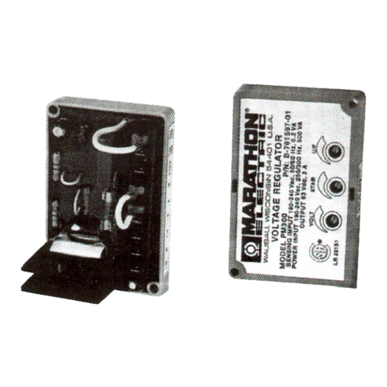
INTRODUCTION The PM300 voltage regulator is an encapsulated electronic voltage regulator that controls the output of a brushless AC generator by regulating the current into the exciter field. SPECIFICATION PM300 REGULATOR Sensing 190-240 Vac 50 / 60 Hz Power Input 190-240 Vac 250 / 300 Hz Burden 500 VA... - Page 3 MOUNTING The PM300 voltage regulator can be mounted in any plane, following is Figure 1 with the mounting dimensions. FIGURE 1 EXCITER POWER CIRCUIT Connect the regulator wire F+ to the generator F+ or Fl field terminal. Connect the regulator wire F - to the generator F - or F2 field terminal. See Figure 2 for typical connection diagram SENSING CIRCUIT Sensing is achieved through terminals E1 and E 4.
- Page 4 FIGURE 2 VOLTAGE ADJUST The screwdriver adjustable potentiometer adjusts the generator output voltage. Adjustment clockwise increases the generator output voltage. When using a remote voltage adjust rheostat, remove the jumper wire across terminals 6 and 7 and install a 2000 ohm 1/2 watt (minimum) rheostat. This will give ±10% voltage variation from the nominal.
-
Page 5: Startup Procedure
FIGURE 3 The PM300 has the roll-off point preset to 58 Hz in the 60 Hz mode and 48 Hz in the 50 Hz mode. To change the roll-off point, adjust engine speed to the desired rated speed. (50 or 60 Hz). Set the voltage to the desired setting at rated speed. -
Page 6: Troubleshooting
TROUBLESHOOTING Symptom Cause Action Residual Voltage -No No voltage at regulator power input Check wiring diagram for Output terminals. proper connections. Defective PMG Shorted PMG Capacitor Field leads Fl, F2 not connected. Connect field leads Fl, F2. Power input leads not connected. Connect power-input leads 3,4.
Need help?
Do you have a question about the Marathon Electric PM300 and is the answer not in the manual?
Questions and answers