Table of Contents
Advertisement
Quick Links
Advertisement
Table of Contents

Related Manuals for Sharkoon USB LANPORT 100

Summary of Contents for Sharkoon USB LANPORT 100
- Page 1 USB LANPORT 100 / 400 Manual english USB LANPORT 100 / 400...
-
Page 2: Table Of Contents
5.2.2 The USB devices context menu 6. Configuration via web interface 6.1 Device Status 6.2 Network 6.3 Reset device 6.4 Factory Default 6.5 Firmware Update 6.6 Password Change 7. Important notes 8. Example of use (Windows XP) USB LANPORT 100 / 400... -
Page 3: Features
Have a good time with our product! SHARKOON Technologies GmbH 1. Features • 1-port (USB LANPort 100) or 4-port (USB LANPort 400) USB server • Allows connecting any USB device to a LAN •... -
Page 4: Parts And Accessories
2. Parts and accessories • USB LANPort (A) • Power adapter (B) • Patch cable (C) • Tools CD incl. software and extensive manual (PDF / D) USB LANPORT 100 / 400... -
Page 5: The Device At A Glance
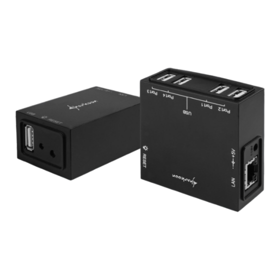
3. The device at a glance USB LANPort 100 USB LANPort 400 – Network connector (RJ-45) – Power connector (5 V / DC) – Reset button – Power LED – USB connector(s) USB LANPORT 100 / 400... -
Page 6: Getting Started
Double-click (left mouse button) this icon to launch the software. Note: You need to install this server software on every PC from which you want to access the USB LANPort. 6. Connect the USB device(s) to the USB port(s) of the USB LANPort. USB LANPORT 100 / 400... -
Page 7: The User Interface
USB stick). Green icon = device available, red icon = device not available – “Search“ button: by clicking (left mouse button) this button the search for devices connected to the USB server will be started – “Config“ (configuration) button (only shown when the USB LANPORT 100 / 400... -
Page 8: The User Interface's Menu Bar
The File menu offers the submenu “Setting“ and the entry “Quit“ . 5.1.1.1 The Setting submenu The Setting submenu contains the entries “Polling Interval“ and „Receive Disconnect Request“ as well as the submenu “Langu- ages“ USB LANPORT 100 / 400... - Page 9 3. The “Receive Disconnect Request” entry: In case a device is already in use by user A and user B wants to access this device simultaneously he can send the follow- ing request to B: USB LANPORT 100 / 400...
-
Page 10: Exiting The Program (Quit Entry)
Select this option to display both the USB Server and connected USB devices in the user interface. 2. The “Devices Only” entry: If this option has been selected, the user interface will only show the attached USB devices. USB LANPORT 100 / 400... -
Page 11: The Help Menu
By right-clicking the USB server entry or the devices entry in the user interface you can access the according context menus. The devices context menu differs depending on whether the de- vice is available (green icon) or blocked (red icon). USB LANPORT 100 / 400... -
Page 12: The Usb Server Context Menu
– Define which port(s) shall be connected during program start-up automatically – “Set“ saves your changes, “Cancel“ discards them – The entries “Backup Firmware“ , “Update Firmware“ , “Change Password“ and “Restart Server“ USB LANPORT 100 / 400... -
Page 13: Backup Firmware
With “Browse” you select the locally saved update version. “Submit” starts, “Cancel” terminates the update pro- cedure. A current firmware version can be found at www.sharkoon.com. 5.2.1.3 Change Password In this input window (see below) you may assign a new pass- word. -
Page 14: Restart Server
You may also force a restart by pressing the reset button on the device. 5.2.2 The USB devices context menu 1. The details entry displays some information regarding the attached devices. USB LANPORT 100 / 400... -
Page 15: Configuration Via Web Interface
“www” put in front) into the browser’s address line. The IP address assigned to the USB server can be found from the user interface of the USB server program: or from the USB server’s context menu: USB LANPORT 100 / 400... - Page 16 Alternatively select the USB server’s entry from the user interface and click “Config“: 4. The browser will display the USB server’s web interface afterwards. USB LANPORT 100 / 400...
-
Page 17: Device Status
Server Name, Manufacturer, Model, Firmware Version and Server Up-Time (time elapsed since server has been started). – This area displays various information regarding the connected device: Device Name, Link Status, Device Status and Current User. USB LANPORT 100 / 400... -
Page 18: Network
With “Server Name” you may define your own server name. To protect the server settings from unwanted changes you need to assign a “Password” . – “Submit” saves your changes while “Clear” will discard them. USB LANPORT 100 / 400... -
Page 19: Reset Device
6.4 Factory Default – Left-click the link to select the respective entry. – To recover the factory default settings enter the pass- word into the “Password” area and confirm by left- clicking the “Factory Default” button. USB LANPORT 100 / 400... -
Page 20: Firmware Update
(see above) into the “Password” area and select the source path of the local update file with “Search” . – “Submit” will confirm and start the update procedure. “Clear” cancels the action. 6.6 Password Change USB LANPORT 100 / 400... -
Page 21: Important Notes
USB memory devices (USB sticks, external hard disk drives etc.) using the “Safely remove hardware” function before terminating the connec- tion via “Disconnect” . The server software will also prompt you with the following note: USB LANPORT 100 / 400... -
Page 22: Example Of Use (Windows Xp)
For this purpose he runs the server software which already has been installed on his system. The user interface of the server software will display the USB server and the associated device. The green icon indicates that the device is available (fig. 1). USB LANPORT 100 / 400... - Page 23 To access the device A selects it (1x left click) and then clicks (left mouse button) the “Connect” button. The operating system will install all required drivers and after- wards the USB stick will be shown as removable medium in the Windows Explorer (fig. 2). fig. 2 USB LANPORT 100 / 400...
- Page 24 “Connect” button is set in grey (fig. 3). fig. 3 Using the devices context menu (fig. 4), B now can send a reque- st (fig. 5) to A who is currently blocking the device. USB LANPORT 100 / 400...
- Page 25 This request will be displayed on A’s screen. A can decide whether he agrees to release the device “Yes” or not “No” . As soon as A has released the device, B will receive the follow- ing prompt and can “Connect” to the device. USB LANPORT 100 / 400...
- Page 26 When B does not need the device any longer he can cancel the connection via “Disconnect” and release the device for further usage. USB LANPORT 100 / 400...
- Page 27 All named products and descriptions are trademarks and/or re- gistered trademarks of the respective manufacturers and are ac- cepted as protected. As a continuing policy of product improvement at SHARKOON, the design and specifications are subject to change without prior notice. National product specifications may vary.
Need help?
Do you have a question about the USB LANPORT 100 and is the answer not in the manual?
Questions and answers