Table of Contents
Advertisement
Quick Links
Advertisement
Table of Contents

Related Manuals for FULLY WIRED ELECTRONICS Mini-Logic

Summary of Contents for FULLY WIRED ELECTRONICS Mini-Logic
- Page 1 Fully Wired Electronics - Mini-Logic User Manual...
-
Page 2: Table Of Contents
Fully Wired Electronics - Mini-Logic User Manual v1.0 Contents: Limited Warranty………………….................2 Installation and Safety………..................3 Foreword…........................4 Module Overview…………………………………………………….........5 Logic Gates in Practice……………………………………………………………………..7 NOT Gates……………………………………………………………………………..7 AND Gates……………………………………………………………………………..8 NAND Gates…………………………………………………………………………...9 OR Gates……………………………………………………………………………..10 NOR Gates……………………………………………………………………………11 XOR Gates……………………………………………………………………………12 XNOR Gates………………………………………………………………………….13 Technical Specifications.....................14... -
Page 3: Limited Warranty
Fully Wired Electronics deems to be at the fault of the user are not covered by this limited warranty. Normal service rates will be applied. -
Page 4: Installation And Safety
Fully Wired Electronics - Mini-Logic User Manual v1.0 Installation and Safety: Prior to installing and uninstalling this product, please ensure that your Eurorack power supply is turned OFF. Installing or uninstalling this product without doing so is potentially dangerous, running the risk of causing damage to your equipment and electrocuting yourself. -
Page 5: Foreword
Fully Wired Electronics - Mini-Logic User Manual v1.0 Foreword: Thank you for purchasing the Fully Wired Electronics - Mini-Logic. We value all of our customers for their support. Your purchase is greatly appreciated! Special thanks to everyone who was involved during the development and... -
Page 6: Module Overview
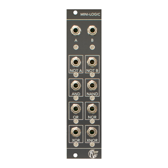
User Manual v1.0 Module Overview: The Fully Wired Electronics - Mini-Logic is a 2 input, 8 output 6HP Boolean Logic module, outputting all Boolean Logic types according to the state of both gate inputs. The module features AND, NAND, OR, NOR, XOR, XNOR and two NOT outputs. - Page 7 Mini-Logic. Each of the outputs are visualised on the module through the use of rectangular boxes around each of the output jack sockets. The output states for each of the logic types are indicated through the LEDs located below its associated output jack socket.
-
Page 8: Logic Gates In Practice
Fully Wired Electronics - Mini-Logic User Manual v1.0 Logic Gates in Practice: NOT Gates: NOT gates are the simplest of the 7 logic types, as they have a single input and a single output. This gate type simply outputs an inverted copy of the signal at its input. -
Page 9: And Gates
Fully Wired Electronics - Mini-Logic User Manual v1.0 AND Gates: The output of the AND gate remains in a low (0) state, whilst both of the inputs are in a logical low (0) state. The same is true if only one of the inputs receives a signal and enters a logical high (1) state. -
Page 10: Nand Gates
Fully Wired Electronics - Mini-Logic User Manual v1.0 NAND Gates: NAND Gates build upon AND gates through incorporating NOT gates, causing the inverse operation. The output of a NAND gate will remain in a logical high (1) state until both inputs (in the case of a two input NAND gate) are in a high (1) state, at which point the output will turn to a logic low (0) state. -
Page 11: Or Gates
Fully Wired Electronics - Mini-Logic User Manual v1.0 OR Gates: The output of an OR gate will be high (1) if either of the inputs are high (1). The same is true if both inputs are simultaneously in a high (1) state. For the output of an OR gate to be low (0), both inputs need to simultaneously be low (0), as seen in Fig. -
Page 12: Nor Gates
Fully Wired Electronics - Mini-Logic User Manual v1.0 NOR Gates: NOR Gates have the inverse operation of OR Gates and incorporate NOT gates to activate this. The output state of a NOR gate, by default, will be high (1), as seen within Fig. -
Page 13: Xor Gates
Fully Wired Electronics - Mini-Logic User Manual v1.0 XOR Gates: As seen in Fig. 7, the output of a XOR gate will be low (0) by default, not both inputs are in a low (0) state. If either inputs, but not both, are in a high (1) state, the output of the XOR gate will also be in a high (1) state. -
Page 14: Xnor Gates
Fully Wired Electronics - Mini-Logic User Manual v1.0 XNOR Gates: XNOR Gate is an inverted version of a XOR Gate, achieved through incorporating NOT gates. When both inputs are in a low (0) state, the output will be in a high (1) state. -
Page 15: Technical Specifications
Fully Wired Electronics - Mini-Logic User Manual v1.0 Technical Specifications: ● Module Format: 3U ● Module Width: 6HP ● Module Depth: 32mm ● Power: ● +12v current draw: 15mA ● -12v current draw: 0mA ● +5v current draw: 0mA...
Need help?
Do you have a question about the Mini-Logic and is the answer not in the manual?
Questions and answers