Flexiheat SF 14 EVOLUTION NOx Instructions For Installation, Use And Maintenance Manual
Room sealed chamber water heater
Hide thumbs
Also See for SF 14 EVOLUTION NOx:

Related Manuals for Flexiheat SF 14 EVOLUTION NOx


Summary of Contents for Flexiheat SF 14 EVOLUTION NOx
- Page 1 Installation, Use and Maintenance Manual for model SF 14 EVOLUTION NOx Room sealed chamber water heater 0476 SF 14 EVOLUTION NOx - RAD - ING - Manuale - 2009.1_HDIMS13_firm.05_R9...
-
Page 2: Table Of Contents
TABLE OF CONTENTS TABLE OF CONTENTS INTRODUCTION 1. INSTALLER SECTION 1.1. INSTALLATION 1.1.1. GENERAL INSTALLATION WARNINGS 1.1.2. WATER HEATER LOCATION ENVIRONMENTAL REQUIREMENTS 1.1.3. REFERENCE LEGISLATION 1.1.4. UNPACKING 1.1.5. OVERALL DIMENSIONS 1.1.6. HYDRAULIC CONNECTIONS 1.1.7. POSITIONING AND MINIMAL TECHNICAL SPACES 1.1.8. HYDRAULIC CONNECTION 1.1.9. - Page 3 TABLE OF CONTENTS 2.2.12. ERROR CODES 2.2.13. FUNCTION CODES 2.2.14. DELAY CODES 2.2.15. INFO MENU DISPLAY DATA 2.2.16. POSITIONING OF THE ELECTRODE 2.2.17. GAS CONVERSION 3. USER SECTION 3.1. USE 3.1.1. GENERAL USE WARNINGS 3.1.2. CONTROL PANEL 3.1.3. DISPLAY ICONS 3.1.4.
-
Page 4: Introduction
INTRODUCTION INTRODUCTION WARNING › Device: this term is used referring to the water heater. Before starting any operation it is mandatory to read this instruction manual, in relation to the DANGER activities to be carried out as described in each It identifies an information related to a relevant section. - Page 5 INTRODUCTION MANUFACTURER WARRANTY AND RESPONSIBILITY The technical and functional features of the device are ensured by its use in compliance: W ith maintenance instructions contained manuals accompanying the product, the content of which the customer certifies that he is aware; With the conditions and purposes to which assets of the same type are intended.
-
Page 6: Installer Section
1. INSTALLER SECTION 1. INSTALLER SECTION The installation operations described in this section should be performed only by qualified personnel, having the appropriate technical training in the field for the installation and maintenance of components of civil and industrial domestic hot water production and heating plants. -
Page 7: Installation
1. INSTALLATION 1.1. INSTALLATION 1.1.1. GENERAL INSTALLATION › The device is suitable for use with the type of gas WARNINGS available by checking the water heater data plate (placed on the inner side of the front casing. ATTENTION This machine may be used only for the ›... -
Page 8: Reference Legislation
1. INSTALLATION instructions and not protected adequately from the freeze. 1.1.3. REFERENCE LEGISLATION The installation must be realized according to the requirements of current legislation and in compliance with local technical regulations, according to the indications of the good technique. -
Page 9: Unpacking
1. INSTALLATION 1.1.4. UNPACKING WARNING Please unpack the water heater just before installing it. The Company is not responsible for the damages caused to the device due to incorrect storage. WARNING The packing elements (cardboard box, wooden crate, nails, fasteners, plastic bags, expanded polystyrene, etc.) must be kept out of the reach of children as they may be dangerous. -
Page 10: Overall Dimensions
1. INSTALLATION 1.1.5. OVERALL DIMENSIONS 1.1.6. HYDRAULIC CONNECTIONS D.H.W. OUTLET Ø 1/2 Ø 3/4 COLD WATER INLET Ø 1/2... -
Page 11: Positioning And Minimal Technical Spaces
1. INSTALLATION 1.1.7. POSITIONING AND MINIMAL TECHNICAL SPACES The water heater must be installed only on a vertical solid wall, able to sustain its weight. In order to allow the access inside the water heater for maintenance operations, you have to respect the minimum technical spaces indicated in figure To facilitate the installation, the water heater is provided with a jig that allows setting in advance the... -
Page 12: Hydraulic Connection
1. INSTALLATION 1.1.8. HYDRAULIC CONNECTION °f. However, please check the characteristics of the water used and install suitable treating devices. DANGER Make sure that the tubes of the water and The heat exchanger coil cleaning frequency heating plant are not used as grounding system for depends on the hardness of the supply water and on the electrical plant. -
Page 13: Frost Protection Kit
1. INSTALLATION 1.1.9. FROST PROTECTION KIT Thanks to the optional electrical heating elements (code 50-00106), it is possible to protect the water heater up to an outside temperature of °C. The kit of electrical heating elements is a frost protection that is triggered when the water probe detect a temperature of 4°C to heat up the exchanger pipes to a temperature of 8°C. -
Page 14: Gas Connection
1. INSTALLATION 1.1.10. GAS CONNECTION 1.1.11. ELECTRICAL CONNECTION DANGER DANGER In order to connect the gas connector of The equipment is electrically safe only the boiler to the supply pipe use a stop seal of an if it is properly connected to an efficient grounding appropriate size and material. -
Page 15: Optional Electrical Connections
1. INSTALLATION 1.1.12. OPTIONAL ELECTRICAL CONNECTIONS DISABLING THE D.H.W. MODE BY CONTACT It is possible to enable/disable the request to turn on the burner in DHW mode, when there is a connection (for example of a storage tank time clock, a temperature thermostat or a solar control box) on the ‘CS’, D.H.W. -
Page 16: Flue Systems
1. INSTALLATION 1.1.13. FLUE SYSTEMS WARNING > In order to ensure proper operation and > efficiency of the device you have to connect the choosen flue system to the flue exhaust duct using appropriate flue systems for traditional water heaters. WARNING cannot plastic... -
Page 17: Types Of Installation
1. INSTALLATION 1.1.14. TYPES OF INSTALLATION DISCHARGE OF COMBUSTION PRODUCTS FOR B-TYPE DEVICES. For this type of boiler are available the following fumes discharge configurations: B22, C12 and C32 The gas devices, provided with connection for (see Fig. 1). fumes exhaust tube, must be directly connected to efficient chimneys or fume exhaust ducts: ›... - Page 18 1. INSTALLATION · permanent openings on the external walls of the location (windows); · single or collective, ramified ventilation ducts. The openings on the external walls of the location must respect the following requirements: · have a net overall free passage section of at least 6 cm for every kW of heat capacity installed with a minimum of 100 cm...
-
Page 19: Types Of Flue Systems
1. INSTALLATION Warning! A fixed Ø 40mm flue insert is 1.1.15. TYPES OF FLUE SYSTEMS factory fitted on the flue inspection flange (Fig.1) KIT A - HORIZONTAL CONCENTRIC FLUE KIT Ø60/100 mm. See the next paragraph table to select the It allows the flue exhaust and the air intake from external correct flue insert to be installed, among wall. - Page 20 1. INSTALLATION FLUE INSERTS FOR THE CONCENTRIC FLUE KIT Ø60/100 Maximum discharge length - Ø60/100 mm FLUE INSERT Ø42 mm in the from 0,5 to 1 m - Ø60/100 mm diaf. pos. flue inspection flange (Do NOT install an adjustable flue diaphragm) FLUE INSERT Ø44 mm in the from 1 to 2 m - Ø60/100 mm diaf.
- Page 21 1. INSTALLATION WARNING! IN CASE THE FLUE EXHUAST PIPE KIT B - HORIZONTAL TWIN PIPE FLUE KIT TERMINATES TO AN OUTSIDE WALL INSTEAD Ø80/80mm The twin pipes system allows the flue exhaust OF A FLUE DUCT, IT IS MANDATORY TO INSERT through the flue exhaust pipe and the air intake THE FLUE TERMINAL PART NO.
- Page 22 1. INSTALLATION FOR TWIN PIPES SYSTEM In order to adjust the flue diaphragms, proceed as follows (see fig.2) › Depending on the maximum exhaust length in use, see the corresponding diaphragm regulation in the table below; › Move the reference index (A-fig.2) by sliding along the graded index (B-fig.2), depending on the adjustment to be made;...
-
Page 24: Support Center Section
1. SUPPORT CENTRE SECTION 2. SUPPORT CENTER SECTION All operations described below relative to first start- up, maintenance and replacement should be performed only by qualified personnel... -
Page 25: Commissioning
2. COMMISSIONING 2.1. COMMISSIONING 2.1.1. COMMISSIONING › make sure that there are no flammable liquids PRELIMINARY OPERATIONS or materials near the device; The first start-up operations consist in checking › open the water heater gas tap and make sure the correct installation, adjustment and operation that there are no gas leaks upstream from the of the device. -
Page 26: Water Heater Ignition
2. FIRST START-UP 2.1.2. WATER HEATER IGNITION Proceed with water heater commissioning as follows: › Power the water heater. › Open the gas tap. › ignite the unit by pressing the button ‘ ’. › When DHW is needed, the burner will switch on. The operation will be confirmed by the blinking symbol ‘... -
Page 27: Gas Pressure Check And Calibration
2. FIRST START-UP 2.1.2. GAS PRESSURE CHECK AND › Make sure that the gas pressure read on the CALIBRATION pressure gauge complies with the information contained in the chapter “HEAT CAPACITY / GAS With this procedure, it is possible to adjust the PRESSURE DIAGRAM”. -
Page 28: Total Gas Valve Calibration
2. FIRST START-UP 2.1.3. TOTAL GAS VALVE CALIBRATION › Press the ‘ ’ key to go to parameter ‘q01’, which corresponds to the minimum power value. In the event of replacement of the gas valve or the electronic board, proceed with total calibration of ›... -
Page 29: Co2 Value Check And Calibration
2. FIRST START-UP 2.1.4. CO2 VALUE CHECK AND CALIBRATION WARNING The CO value should be checked with the casing assembled. To check and calibrate the CO value to maximum and minimum power proceed as follows: fig. 1 FOR MAXIMUM POWER Activate the chimney sweeper function by pressing the ‘... -
Page 30: Accessing And Programming The Parameters
2. FIRST START-UP 2.1.5. ACCESSING AND PROGRAMMING THE PARAMETERS To access the parameters menu and adjust their values, follow the procedure below: When the operating mode is anything other than OFF, press and hold the ‘ ’ key for 10 seconds and wait for the flashing message “tS”... - Page 31 2. FIRST START-UP Keep key ‘ ’ pressed until the display shows the parameter value. Use the keys ‘ ’ and ‘ ’ of the domestic circuit to change the value of the parameter. To make the adjustment made operational, press the ‘...
- Page 32 2. FIRST START-UP To exit from the parameter, press the ‘ ’ key just once. To exit from the parameters menu, press the ‘ ’ key just once; the message “tS” will appear. Press and hold the ‘ ’ key for 10 seconds to instead exit from the Installer menu.
-
Page 33: Hdims13 Parameters Table
2. FIRST START-UP 2.1.6. HDIMS13 PARAMETERS TABLE PARAMETER DESCRIPTION RANGE FUNCTION OPERATING TYPE SELECTION 2 - 5 2 = MONOTHERMAL INSTANT 3 = HEATING ONLY 4 = ACCUMULATION 5 = WATER HEATER GAS TYPE SELECTION 0 - 1 0 = METHANE ATTENTION: READ INSTRUCTION... - Page 34 2. FIRST START-UP PARAMETER DESCRIPTION RANGE FUNCTION DJUSTMENT OF MAXIMUM POWER IN D.H.W. 0 - 100 THE VALUE IS EXPRESSED IN PERCENTAGE USE THIS PARAMETER TO SET THE MAXIMUM GAS (PRE-SET TO 100) PRESSURE OF THE BURNER IN D.H.W. PHASE. [SEE THE CHAPTER ‘HEAT CAPACITY / GAS PRESSURE DIAGRAM’].
- Page 35 2. FIRST START-UP PARAMETER DESCRIPTION RANGE FUNCTION MINIMUM FAN SPEED 100 - 140 DO NOT MODIFY (PRE-SET TO NATURAL GAS) STARTING STEP ADJUSTMENT 110 - 140 DO NOT MODIFY (PRE-SET TO NATURAL GAS)
-
Page 36: Heat Input/ Gas Pressure Diagram
2. FIRST START-UP 2.1.7. HEAT INPUT/ GAS PRESSURE DIAGRAM GAS PRESSURE (mbar) GAS TYPE MINIMUM GAS PRESSURE MAXIMUM GAS PRESSURE mbar mbar 35,5... -
Page 37: Maintenance
2. MAINTENANCE 2.2. MAINTENANCE 2.2.7. GENERAL MAINTENANCE detection and light up electrode from incrustations WARNINGS paying attention to respect the distances with respect to the burner (see chapter “POSITIONING DANGER OF THE ELECTRODE”); Before each components cleaning or replacement operation, ALWAYS cut off the POWER, ›... -
Page 38: Technical Data
2. MAINTENANCE 2.2.8. TECHNICAL DATA Model SF 14 Evolution NOx CE certification 0476CU3685 Gas category II2E 3P Flue system type type B22-C12-C32 Heat Input max (D.H.W.) 24,5 Heat Input min (D.H.W.) 10,5 Maximum combustion efficiency 90,1 Minimum combustion efficiency 93,6 Flue efficiency losses with burner on (Heat Input max.) - Page 39 2. MAINTENANCE from 0,5+0,5+F149:F167 m - Horiz. Twin diaf. pos. FIXED DIAPHRAGM Ø40 mm in the flue inspection flange adjustable diaphragm on the air intake set at 2 from 0,5+0,5 to 4+4 m - Horiz. Twin diaf. pos. FIXED DIAPHRAGM Ø40 mm in the flue inspection flange adjustable...
-
Page 40: Technical Assembly
2. MAINTENANCE 2.2.9. TECHNICAL ASSEMBLY IGNITION / FLAME DECTION ELECTRODE LOW NOX BURNER DOMESTIC HOT WATR SENSOR AIR PRESSURE SWITCH SAFETY THERMOSTAT HEAT EXCHANGER FLOW SWITCH GAS VALVE... -
Page 41: Hydraulic Diagram
2. MAINTENANCE 2.2.10. HYDRAULIC DIAGRAM C. DOMESTIC HOT WATER OUTLET G. GAS F. COLD WATER INLET FLUE HOOD HEAT EXCHANGER LIGHT UP/DETECTION ELECTRODE LOW NOX BURNER DOMESTIC HOT WATR SENSOR SAFETY THERMOSTAT FLOW SWITCH GAS VALVE... -
Page 42: Wiring Diagram
2. MAINTENANCE 2.2.11. WIRING DIAGRAM EA/R HDIMS13 ro-ne ro-ne 220 V 50 Hz EA/R: LIGHT UP/DETECTION ELECTRODE EV: ELECTRIC FAN NE: BLACK AR: ORANGE CKR: FROST PROTECTION TRA:START-UP TRANSFORMER HE: HALL EFFECT SENSOR BI: WHITE L: LINE CONTACT THROUGH MF: MICRO-FLOW SWITCH PA: AIR PRESSURE SWITCH RO: RED N: NEUTRAL... -
Page 43: Accessing The Water Heater
2. MAINTENANCE 2.2.9. ACCESSING THE WATER HEATER For the majority of the control and maintenance operations you have to remove one or more panels of the casing. The side panels can be removed only after removing the front panel. To intervene on the front of the water heater proceed as follows: ›... -
Page 44: Accessing The Electronic
2. MAINTENANCE 2.2.10. ACCESSING THE ELECTRONIC P.C.B. In order ot intervene on the wirings of the control panel, please proceed as follows: DANGER Cut off the voltage from the main switch. › Grab at the same time the support brackets of the control panel (fig. -
Page 45: Emptying The Domestic System
2. MAINTENANCE 2.2.11. EMPTYING THE DOMESTIC SYSTEM If there is freezing risk, you have to empty the domestic system as follows: › close the main supply tap of the water supply network; › open all cold and hot water taps; ›... -
Page 46: Error Codes
2. MAINTENANCE 2.2.12. ERROR CODES CODE FAULT POSSIBLE CAUSE SOLUTION RESET FLAME BLOCK NO FLAME LIGHT UP PRESS RESET ‘ ’ KEY GAS MISSING; CHECK THE ADDUCTION NETWORK; MASS OR BROKEN START-UP REPLACE IT; ELECTRODE; GAS VALVE BROKEN; REPLACE IT; PRESSURE TOO HIGH AT THE CHECK THE MAXIMUM ADJUSTMENT INPUT OF THE GAS VALVE... - Page 47 2. MAINTENANCE CODE FAULT POSSIBLE CAUSE SOLUTION RESET DOMESTIC CIRCUIT PROBE BROKEN OR INCORRECTLY REPLACE IT; AUTOMATIC. CALIBRATED PROBE (RESISTANCE VALUE 10 KOHM AT 25 °C NTC); DISCONNECTED OR WET CHECK THE WIRING. PROBE CONNECTOR. GAS VALVE AFTER THE BURNER SHUTS IF NOTHING OCCURS AFTER RESET, PRESS DOWN, THE SYSTEM CHECKS...
- Page 48 2. MAINTENANCE CODE FAULT POSSIBLE CAUSE SOLUTION RESET ELECTRIC FAN INCORRECT CONNECTION OF CHECK ELECTRICAL CONNECTION; AUTOMATIC. THE ELECTRIC FAN; ELECTRIC REPLACE IT. FAN BROKEN. HALL EFFECT SENSOR WRONG CHECK ELECTRICAL CONNECTION; CONNECTION; BROKEN REPLACE IT. SENSOR FLAME LOSS THE FLAME GOES OUT 6 TIMES PRESS IN 10 MINUTES.
- Page 49 2. MAINTENANCE PROCEED AS FOLLOWS TO MANUALLY RESET THE BLOCKED FAULTS: Press the ‘ ’ key to deactivate the fault. Remove and restore power to the boiler, pressing and holding the ‘ ’ key. As soon as the flame lights up, activate the chimney sweep function by simultaneously pressing and holding the ‘...
-
Page 50: Function Codes
2. MAINTENANCE 2.2.13. FUNCTION CODES CODE FUNCTION DESCRIPTION CHIMNEY SWEEP ACTIVE XX (NUMBER SIMULTANEOUSLY PRESS AND HOLD THE ‘ ’ KEYS TO ACTIVATE. BETWEEN 00 THE DISPLAY WILL SHOW THE MAXIMUM PERCENTAGE VALUE SET BY THE D.H.W. AND 100) CIRCUIT. THIS VALUE CAN BE EDITED DIRECTLY BY PRESSING THE ‘ ’... -
Page 51: Info Menu Display Data
3. USE 2.2.15. INFO MENU DISPLAY DATA To view the water heater data from the info menu: › When the operating mode is anything other than OFF, press and hold the ‘ ’ key for 10 seconds and wait for the flashing message “tS” to appear on the display, then release the key. You have now entered into the Installer menu. -
Page 52: Positioning Of The Electrode
2. MAINTENANCE 2.2.16. POSITIONING OF THE ELECTRODE Check that the electrode is positioned at the right distance from the burner and with the correct inclination, see fig. 1. 3÷5 mm 3÷5 mm fig. 1... -
Page 53: Gas Conversion
2. MAINTENANCE 2.2.17. GAS CONVERSION the other inside the front panel of the water heater, near the data plate. On the latter, data WARNING relating to the old type of gas in use must be Make sure that the gas adduction tube is deleted with a permanent marker. -
Page 54: User Section
1. USER SECTION 3. USER SECTION The operations described in this section are addressed to all those who will use the machine. The machine must be used and accessed only by qualified operators that fully read and understood the User section, paying particular attention to the warnings. -
Page 55: Use
3. USE 3.1. USE 3.1.1. GENERAL USE WARNINGS › DO NOT use electrical switches, the telephone or any other device that might generate electrical WARNING discharges or sparks; Before starting the water heater the User must make sure that the First start-up certificate has ›... -
Page 56: Control Panel
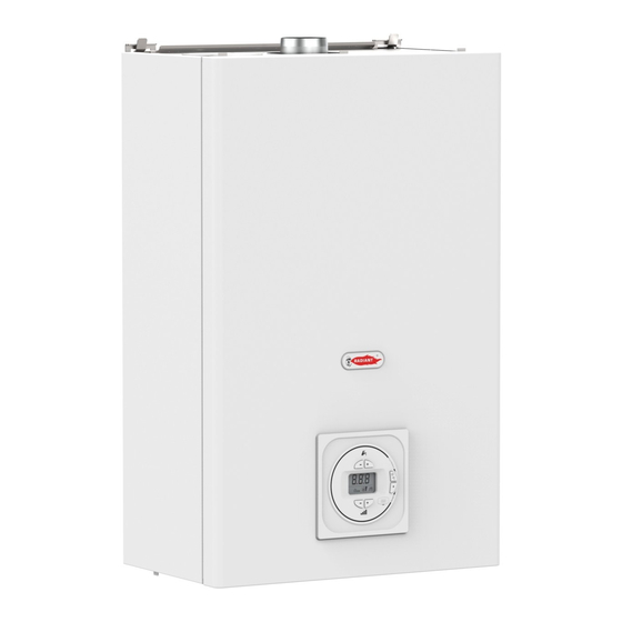
3. USE 3.1.2. CONTROL PANEL DOMESTIC WATER TEMPERATURE ADJUSTMENT KEYS DISPLAY OPERATING MODE SELECTION KEY: D.H.W. ONLY / OFF RESET KEY: ANOMALY RESET POWER ADJUSTMENT KEYS... -
Page 57: Display Icons
3. USE 3.1.3. DISPLAY ICONS INDICATION PARAMETER NUMBER, TEMPERATURE OR INFO CODE DISPLAYED (THE WRITING “SA” WITH INTERMITTENT SIGNAL ON THE DISPLAY, ALTERNATED WITH THE VALUE OF D.H.W. TEMPERATURE INDICATES THAT D.H.W. REQUEST IS ACTIVE); OPERATION IN DOMESTIC MODE ENABLED; fig. -
Page 58: Start-Up
3. USE 3.1.4. START-UP 3.1.7. OFF MODE Before starting the water heater make sure that it is In this mode the water heater no longer meets the D.H.W. powered and that the gas tap below the water heater is requests. The frost protection system remains still active. open. -
Page 59: Error Codes
3. USE 3.1.9. ERROR CODES The boiler might signal some faults by displaying a code. Below you have a list of the codes and of the operations to be performed in order to unlock the boiler. CODE FAULT INTERVENTION FLAME BLOCK MAKE SURE THAT THE BOILER AND CONTACTOR GAS VALVES ARE OPEN. -
Page 60: Function Codes
3. USE 3.1.10. FUNCTION CODES CODE FUNCTION INTERVENTION D.H.W CIRCUIT WAIT UNTIL THE OPERATION A N T I - F R E E Z E IS COMPLETED FUNCTION ACTIVE... -
Page 61: Maintenance
3. USE 3.1.11. MAINTENANCE To ensure proper boiler safety and efficiency, please check the device every year. An accurate maintenance should improve system management. 3.1.12. EXTERNAL CASING CLEANING Clean the cover of the device using a wet cloth and come neutral soap. WARNING DO NOT use abrasive or powder detergents as they might damage the plastic cover and control...
Need help?
Do you have a question about the SF 14 EVOLUTION NOx and is the answer not in the manual?
Questions and answers