
Summary of Contents for Siebring HEATWAVE HW150
- Page 1 5-1-23 OURCE OF EAT! Siebring Manufacturing, Inc. Ph. 712-475-3317 303 S. Main St. PO Box 658 Fax 712-475-3490 George, IA. 51237 www.siebringmfg.com...
-
Page 2: Section 1 - Warranty
Not maintaining the heater according to instructions in this manual or by authorized personnel. Any part altered or abused. Using parts other than those supplied by Siebring Mfg., Inc. to operate this heater Over-firing the unit. Warranty is limited to the original purchaser only, and is void if moved form original site of... -
Page 3: Section 2 - General Information & Hazards
SECTION 2 – GENERAL INFORMATION & HAZARDS 2.1 INTRODUCTION. The Heatwave heater by Siebring Mfg. provides the owner with a dependable, versatile and simple means of burning # 1 and # 2 fuel oils, 10W – 50W used crank case oils and used automatic transmission fluid. Maintained correctly, the heater will give years of service. -
Page 4: Section 3 - Heater Installation
2.12 WARNING. Heatwave heaters by Siebring Mfg. rely on a natural gravity draft. Down drafts (positive) pressures in the heater’s chimney will occur in buildings where negative pressures are created by exhaust fans (car exhaust vents, spray booths, ventilation fans, etc.),... - Page 5 3.8 Use threaded rod rated for applicable heater weight to suspend from a capable load carrying ceiling structure. 3.9 Heater should be installed level for proper operation. Heater installed “not level” could cause a hazardous situation in which personal injury or property damage could result. 3.10 When installing the heater, keep in mind that you must have reasonable access to the unit for servicing.
-
Page 6: Section 4 - Chimney Installation
SECTION 4 – CHIMNEY INSTALLATION 4.1 Failure to provide proper venting of the heater exhaust gases could result in death, serious injury and/or property damage. 4.2 Safe operation of any gravity vented heating equipment requires a proper air make-up system to prevent heater exhaust gases from being drawn into the building which may cause death, serious injury and/or property damage. - Page 7 SECTION 5 – DRAFT 5. The chimney system connected to the Heatwave should have a negative -.02 - .04 W.C. draft when hot (minimum of 10 minute run time) as measured between the heater and the draft control. SECTION 6 – FUEL SUPPLY TANK INSTALLATION 6.1 The fuel supply tank and supply line must be installed in accordance with the National Fire Protection Association requirements, state and local codes and ordinances.
-
Page 8: Index Of Drawings
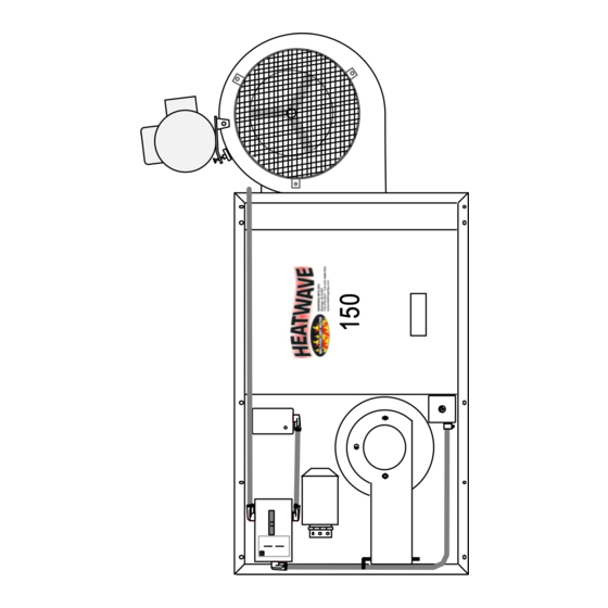
NDEX OF RAWINGS Dimensional view of HW 150 (measurements) Figure Dimensional view of HW 250 (measurements) Figure Dimensional view of HW 350 (measurements) Figure Dimensional view of HW 350 (continued) Figure HeatWave Specifications Figure Kagi Burner Drawing Figure Furnace Installation Example Figure Multi-Wall Chimney Installation Figure... - Page 9 Figure 1...
- Page 10 Figure 2...
- Page 11 Figure 3...
- Page 12 Figure 4...
- Page 13 SIEBRING MANUFACTURING - HEATWAVE SPECIFICATIONS 28-Apr-09 D. Hollander Model HW150 HW250 HW350 BTU Input 150,000 BTU 250,000 BTU 350,000-380,00 BTU max Square Foot Coverage Up to 4,500 sq. ft.* Up to 6,000 sq. ft.* Up to 8,000 sq. ft.* Hourly Fuel Usage 1.1 - 1.5 gallons...
- Page 14 Figure 6...
- Page 15 Figure 7...
- Page 16 MULTIPLE WALL INSULATED CHIMNEY INSTALLATION RAIN CAP * Check footnote for STORM COLLAR chimney clearances ADJ. ROOF FLASHING STORM COLLAR ADJ. ROOF FLASHING JOIST FIRE STOP SPACER JOIST SPACER 2” min. I.C. PIPE LENGTHS (INSULATED CHIMNEY) N.B. CHIMNEY MUST BE INSTALLED WITH AIR GAP AS WALL BAND STATED ON EACH SECTION.
- Page 17 Figure 9...
- Page 18 Figure 10...
- Page 19 Oil Primary Control Yellow wires to cad cell Carlin Primary Control RESET The primary control provides 24 volt thermostat connections. Use # 18-2 wire (Bell wire). At unit start-up, a jumper wire can temporarily be installed to by-pass cad cell to allow for priming of oil lines and pump.
- Page 20 HEATWAVE NOZZLE – TYPICAL (HAGO) ISTRIBUTOR -RING O-Ring - 007 = 5/32 I.D. x O.D. x 9/32 1/16 HEATWAVE NOZZLE – TYPICAL (DELAVAN) ISTRIBUTOR -RING O-Ring - 007 = 5/32 I.D. x O.D. x 9/32 1/16 Normal application: HW150 = 609-5, HW250 = 609-7, HW350 = 609-9 Figure 12...
- Page 21 Figure 13...
-
Page 22: Air Regulator
Pressure Adjustment Knob REGULATOR Flat Washer Main Spring Diaphragm & Stem Stem Guide O-ring Seat & Seat Spring Regulator Body Air Spinner Filter Element Filter Element Retainer Bowl O-ring Filter Bowl Water Drain Figure 14... - Page 23 REGULATOR STEM GUIDE ADJUSTING O-RING SCREW SEAT SEAT SPRING LOCK REGULATOR BODY SPRING WASHER SEAT PLUG SPRING PRESSURE PLASTIC BURNER GAUGE WASHER DIAPHRAGM Looking inside STEM the regulator, cap removed. ⅛” PIPE Figure 15...
- Page 24 Target Flame Characteristics for adjusting oil pressure and troubleshooting “Bushy” flame. Flame does not touch target or chamber walls. Warning: Over-firing the Heatwave will void the warranty and create a fire hazard. Correct maximum flame Target Sooty, smokey Not enough oil flame.
- Page 25 EXPLODED VIEW OF AIR / OIL SOLENOID C Clip Coil Note: When disassembling the valve body, be aware of Spacer the o-ring at the bottom of the seat body. Black o- rings are easily hidden in the pooled black waste oil. Piston Housing (stem)
- Page 26 Figure 18...
- Page 27 Figure 19...
- Page 28 Figure 20...
- Page 29 WEBSTER M17DN-15 Pressure Supply optional gauge port to Burner from tank ⅛” pipe thread ⅛” pipe thread ¼” pipe thread nozzle inlet Single Stage M17DN-15 inlet return auxiliary Inlet return bleeder port ¼” pipe thread (2 pipe system only) ⅜” wrench Attention –...
- Page 30 EBSTER 1RR14004EK13 (REPLACES SUNTEC J-SERIES) RETURN PORT # 1 USED AS RETURN ON 2-PIPE INSTALLATION THIS PORT TO TO ADJUST PRESSURE: BLEED/VENT PUMP REMOVE COVER SCREW. INSERT ⅛” ALLEN WRENCH. THIS PORT TURN CCW TO BELOW NEVER USED PRESSURE DESIRED . TURN CW TO SET DESIRED PREESURE.
- Page 31 Pump to Motor Alignment MOTOR COUPLER COVER PUMP SIDE VIEW MOUNT BOLTS COUPLER HORIZONTAL AXIS SIDE VIEW HORIZONTAL ALIGNMENT VERTICAL AXIS TOP VIEW VERTICAL ALIGNMENT MOTOR SHAFT PUMP SHAFT END ½” Ø END 5/16” Ø LOOK FOR WEAR IN THESE AREAS COUPLER SHAFT INSIDE PUMP MATERIAL...
- Page 32 LENZ FILTER SYSTEM ⅜” 16 UNC Mount Holes To Clean: Remove 4 hex head screws and lower Filter Head filter bowl. Filter element can be ¾” NPT removed by pulling downward with a slight twisting motion. Clean element and bowl with solvent. Be careful not loose, cut or twist bowl Bowl O-ring o-ring upon reinstallation.
- Page 33 Square Motor Must be parallel for proper alignment. Blower Approx. ½” Blower Belt – Alignment and Tension Figure 25...
- Page 34 QUARE REAKER OX – AVE (120V) COMMON 30A Service L1, LINE IN BLOWER GROUND MOTOR I/ON 0/OFF 10 kA 120/240 TO FAN & LIMIT SWITCH BURNER (4 X 4 BOX) Figure 26...
- Page 35 CHEMATIC – IRING YPICAL EATWAVE AN & IMIT WITCH LOWER OTOR BURNER POWER EMOTE UMP & OTOR ECPTACLE 4 X 4 BOX) PUMP POWER Figure 27...
- Page 36 Figure 28...
- Page 37 FIGURE 29...
- Page 38 ONEYWELL AN & IMIT ONTROL L4064B2236 Fan Off: 90 Fan On: 115 High limit: 170 CAUTION HOLD DIAL WHEN SETTING POINTERS 90° 170° 115° LIMIT PUSH PULL AUTO PUSH –MAN LINE PUL L - AUTO Honeywell Thru breaker box to fan motor To breaker in breaker box Thru breaker box to burner Caution: When adjusting set point levers, hold the scaleplate dial to...
- Page 39 HITE ODGERS AN & IMIT ONTROL 5D51-90 Fan Off: 90 Fan On: 115 High limit: 170 Thru breaker box, to burner To breaker in breaker box Thru breaker box to fan motor Caution: When adjusting set point levers, hold the scaleplate dial to keep it from turning and straining the sensing equipment Note: For constant fan operation, slide manual fan switch to “MAN”.
- Page 40 ERMINAL LOCK AIR PRES. SWITCH (TOP) POWER CORD (BLK) PRIMARY CONTROL (BLK) THERMOSTAT RED LAMP TOGGLE SWITCH GREEN LAMP IGNITOR PRIMARY CONTROL (ORG) BURNER MOTOR OIL HEATER AIR SOLENOID OIL SOLENOID AIR SOLENOID IGNITOR PRIMARY CONTROL (WHT) TOGGLE SWITCH SNAP DISK OIL SOLENOID BURNER MOTOR RED LAMP...
- Page 41 Figure 33...
- Page 42 Figure 34...
- Page 43 Figure 35...
- Page 44 Figure 36...
- Page 45 Figure 37...
- Page 46 Figure 38...
- Page 47 Figure 39...
- Page 48 Figure 40...
- Page 49 Figure 41...
- Page 50 Air / Oil Pre-Heater Cartridges ⅞” Wrench, socket or O² sensor socket To test with ohm meter: Heater lead to heater lead should read within 10% of values listed below = good cartridge Under value or an “open” reading = bad cartridge – replace High reading = may be failing - replace 50 watt Oil Pre-heater 288 +/- 10% = 259-316 ohms Kagi Model S250 Burners (HW150/250)
- Page 51 HEATWAVE 150 / 250 PARTS Breaker Box 10. Blower screen 25A Breaker 11. Blower Fan & Limit Switch 12. Drive Pulley Inspection Door 13. Driven Pulley Swing-out Bracket 14. Blower Guard 4 X 4 Junction Box 15. Belt Shell Cleanout Door 16.
- Page 52 HEATWAVE 350 PARTS Note: For burner parts see Kagi manual 10. Blower Breaker Box 11. Drive Pulley 25A Breaker 12. Driven Pulley Fan & Limit Switch 13. Blower Guard Inspection Door 14. Belt Guard Swing-out Bracket 15. Belt 4 X 4 Junction Box 16.
- Page 53 HEATWAVE CLEANING Caution: Wear industrial dust mask and protective clothing. Refer to section 7.06 “Seasonal Cleaning” for more information. 1. Turn thermostat to off or set below room temperature and allow furnace to cool completely. 2. Disconnect power from furnace, turn unit breaker to off. 3.
- Page 54 6. Loosen the brass nuts and clamps around left and right clean-out doors. 7. Remove center nut form right side (chimney) door. 8. Remove left and right clean-out doors to expose exchanger tubes and combustion chamber. 9. Clean all dust and residue with a shop vac. Gentle brushing may be required to remove dust and build up.
- Page 55 CAUTION DO NOT OPERATE WITH BELTGUARD REMOVED WASTE OIL SPECIFICATIONS CAUTION: Never burn Gasoline, Cleaning Solvents, printing fluid, brake fluid or any flammable hydrocarbons in the burner. Do not attempt to burn crude oil or garbage. FUEL USE: # 1 & # 2 Fuel Oil, used (ATF) transmission oil and used motor oils up to 50 S.A.E.
-
Page 56: Start-Up Procedure
CAUTION Minimum clearance to combustible material is 12” from the side walls, 18” from the top. If floor mounted, set on a non-combustible flooring material. Do not block or have anything obstructing the incoming air at the blower. The minimum circuit amperage is 10 amp. Rev. - Page 57 CAUTION WHEN OPENING INSPECTION DOOR PORT MAY BE HOT OPEN DOOR SLOWLY WEAR SAFETY GLASSES KEEP FACE AWAY PROTECT HANDS Figure 49...
Need help?
Do you have a question about the HEATWAVE HW150 and is the answer not in the manual?
Questions and answers