Table of Contents
Advertisement
Quick Links
Advertisement
Table of Contents

Summary of Contents for STM NEXO M28
- Page 1 DP7153-01-DI M28 / M28-I User manual...
-
Page 2: Table Of Contents
Is in conformity with the provisions of the following directive 2014/35/UE (Low Voltage Directive) including all applicable amendments: Applied rules and standards: EN 12100, EN 13155, EN 62368 Plailly, June, 2014 Joseph CARCOPINO, R&D Director Page 2 / 28 STM-M28 / M28-I... -
Page 3: Warnings
Recycling helps spare natural resources. For more information about the recycling of this product, please contact your local city office, your household waste disposal service or your reseller. Page 3 / 28 STM-M28 / M28-I... -
Page 4: Equipment
M28 modules, from 0.2° to 15°. M28-I RIGAV Fix, front rigging points CompassRig Fix (STI-M28CMP) allows pre-setting of inter-cabinet angle value between M28 modules, from 0.2° to 15°. Page 4 / 28 STM-M28 / M28-I... -
Page 5: Description
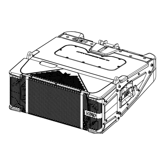
DESCRIPTION DESCRIPTION → The M28 is a compact full-range 2 ways speaker. → M28 can be used alone or with STM-M46, STM-B112, STM-S118, MSUB18 → Versions: • STM-M28-120: Touring application, 120° horizontal coverage • STM-M28-90: Touring application, 90° horizontal coverage •... -
Page 6: Preset
Preset LF Main, 180 Hz – 900 Hz. • Preset HF Downfil, 900 Hz – 20 kHz. • Preset LF Downfil, 120 Hz – 900 Hz. • Preset LF Downfil, 180 Hz – 900 Hz. Page 6 / 28 STM-M28 / M28-I... - Page 7 PRESET M28 + B112 M28 + S118 Page 7 / 28 STM-M28 / M28-I...
- Page 8 PRESET M28 + MSUB18 Page 8 / 28 STM-M28 / M28-I...
-
Page 9: Hf Directivity
Remove the 8 screws and the front grid Unscrew the 3 screws and remove the first FLG28120, unscrew 3 screws and remove the second. Position the first FLG28090 with 3 screws, position the second with 3 screws. (Use provided screws) Page 9 / 28 STM-M28 / M28-I... -
Page 10: Crossover Frequency
Position the first FLG28120 with 3 screws, position the second with 3 screws. (Use provided screws) CROSSOVER FREQUENCY → 60 Hz: Full range application. → 85, 120, 180 Hz: Use with MSUB18 / S118. Page 10 / 28 STM-M28 / M28-I... - Page 11 If locking pins appear to be going inwards in relation to rigging plates, cabinets must not be flown. Ensure all REDLock safety pins are locked into handle holes. Check rear quick release pins are fully engageg and locked. Page 11 / 28 STM-M28 / M28-I...
- Page 12 Attach the Compass to the bottom M28-I, using the D12x80 screw and secure with the M10 nut. Adjust the appropriate angle by using D10x25, secure with nut M8 0.2° 0.8° 2° 4° 8° 10° 12.5° 15° Page 12 / 28 STM-M28 / M28-I...
-
Page 13: Accessories
M28. Lock the lateral springs pins inside the LBUMPM28. Insert the quick release pin at the back. Lift the assembly. Refer to the Product Data Sheet Page 13 / 28 STM-M28 / M28-I... - Page 14 (max 1700kg) Limited to 18x M28 Kelping Beam Place KBEAM on XBOW. Insert the steel pin and insert the safety pin, rotate its ring to lock safety. Refer to the Product Data Sheet Page 14 / 28 STM-M28 / M28-I...
- Page 15 Tilt beam 1 rigging point Negative Tilt Positive Tilt Place VBUMP on XBOW Insert the steel pin and insert the safety pin, rotate its ring to lock safety. Refer to the Product Data Sheet Page 15 / 28 STM-M28 / M28-I...
- Page 16 BTBUMP hole. Refer to the Product Data Sheet GTT-BCCH / STT-BCCH3 Compression chain 2 Tons Compression chain3 Tons Refer to the Product Data Sheet Page 16 / 28 STM-M28 / M28-I...
- Page 17 Chain Lever Hoist 750 kg Chain Lever Hoist 1.5 Ton Refer to the Product Data Sheet VXT-LIS-REC Laser Inclinometer Set. Insert the assembly, push forward until it locks. Refer to the Product Data Sheet Page 17 / 28 STM-M28 / M28-I...
- Page 18 ACCESSORIES STACKING STT-GSTK (9x M28 max) Stabilizer for STM Dolly. Refer to the Product Data Sheet ACCESSORIES STI-IPCOV28 Waterproof Housing for STM-M28. Refer to the Product Data Sheet STT-FLG28090/28120 Flange 90° M28. Flange 120° M28. Refer to the Product Data Sheet...
- Page 19 Single Dolly with STT-GSTK Double Dolly Refer to the Product Data Sheet STT-DROOF Dolly roof Refer to the Product Data Sheet STT-DCOVER2812 Cover 2x 6M28 on Dolly02 Refer to the Product Data Sheet Page 19 / 28 STM-M28 / M28-I...
- Page 20 ACCESSORIES STT-DOLLYKIT28 M28 Adapter – Dolly STM Lock the CompassRig before. Use the back and side guides to position the cabinets . Lock cabinet on the dolly with RedLock Pull upwards the red latch and at the same time, pull the RedLock...
-
Page 21: Array Eq
The ArrayEQ allows to adjust the system frequency response in its lower range (see curves below, with different ArrayEq values): 28 rray (d ) ad usting Fre uency ( 28 rray (d ) ad usting Fre uency ( Page 21 / 28 STM-M28 / M28-I... -
Page 22: Maintenance
Remove the 10 screws (Torx10) and the front grid. Unscrew the 3 screws (Torx25) to remove the flange. Remove 8’’ driver (Torx25). Reassembly. Positionning the 8’’ connector on the guide side. Use the screws provided. Replace the flange and the grid. Page 22 / 28 STM-M28 / M28-I... - Page 23 When you remove the diaphragm, pay attention there may be a diaphragm. spacer between the motor ans the diaphragm. Use the screws provided. LF: red (+) / black (-) HF: orange (+) / grey (-) Page 23 / 28 STM-M28 / M28-I...
- Page 24 Remove the 5 screws and the cover. (Use the provided screws for the reassembly). Compass !! Once a year, clean the parts and blow compressed air. Remove screw and nut. Dismounting downwards, pay attention with washers and spacers Page 24 / 28 STM-M28 / M28-I...
- Page 25 M28 COVER 05VXTCBX640N-EM BLACK TORX BUTTON HEAD SCREW 6X40. LOCTITE MEDIUM (x10) 05PM28CATAR M28 BACK HANDLE 05HPA14F-16 DRIVER 1.4" 16 OHM 05NH14-F16R/K HPA14F-16 DIAPHRAGM 05STM.M28-RGAR M28 REAR RIGGING COMPLETE 05STI-M28CMP 05STM.M28-FPC M28 PASSIVE FILTER Page 25 / 28 STM-M28 / M28-I...
-
Page 26: Technical Specifications
Front finish Perforated Dark Grey Metal Grille 2x side handles Fittings 1x rear handle 2x NLT4-MDV SpeakON – 4 poles Connector Weight 37 kg / 82 lb ID Classification IP54 with STI-IPCOV28 10,5 Dimensions Page 26 / 28 STM-M28 / M28-I... -
Page 27: User Notes
USER NOTES USER NOTES Page 27 / 28 STM-M28 / M28-I... - Page 28 USER NOTES Tel: +33 3 44 99 00 70 NEXO S.A. Fax: +33 3 44 99 00 30 E-mail: info@nexo.fr Parc d’activité de la Dame Jeanne nexo-sa.com F-60128 PLAILLY Page 28 / 28 STM-M28 / M28-I...
Need help?
Do you have a question about the NEXO M28 and is the answer not in the manual?
Questions and answers