Advertisement
Quick Links
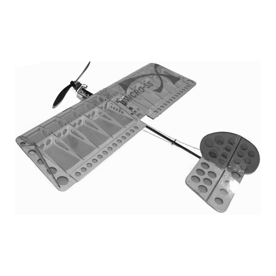
Millennium RC presents Micro SSX Build Kit
Introduction:
This is the Micro SSX™ build-it-yourself kit. It is identical to the ARF version with some
enhancements to make it easier to build. All the parts are laser cut and interlocking so no pins are
needed to assemble this kit. The wing can be assembled in ½ an hour by most modelers.
The MicroSSX™ is a miniature version of the Millennium R/C Slow Stick X™ Electric Park
Flyer.
It is a fun-to-fly fully aerobatic electric R/C airplane that can be taken anywhere! Fly it indoors
or out!!
Adult supervision recommended for children 15 and under. R/C Airplanes should be flown
following safety guidelines provided by the AMA (Academy of Model Aeronautics).
CAUTION: This is not a toy!
Recommendations:
1. Read through each step before starting assembly.
2. After removing all the pieces from packaging, inspect to make sure there are no broken or
missing parts.
3. Check off each completed step to help keep from losing your place.
Millennium R/C assumes no responsibility for any accident or injury to persons or damage to property.
TM
DISCLAIMER
Dimensions: 21 ½" wing span
Flying Weight: 4 ½ -5 ¼ oz.
(with recommended setup)
:
Advertisement

Summary of Contents for Millennium R/C Micro-SS Micro SSX
- Page 1 2. After removing all the pieces from packaging, inspect to make sure there are no broken or missing parts. 3. Check off each completed step to help keep from losing your place. DISCLAIMER Millennium R/C assumes no responsibility for any accident or injury to persons or damage to property.
- Page 2 Parts provided in Micro SSX Build Kit If you should find a part missing or damaged, or have any questions about assembly, please contact us: Millennium R/C 12859 Lower River Blvd., Orlando, FL 32828 Phone: 407-208-9745 / Fax: 866-799-2372...
- Page 3 Assembly Instructions: Completed wing frame 1. Cut - don’t break the balsa and plywood parts from the parts sheets. Breaking the parts out of the sheets can damage the parts. Remove all “W” balsa parts and P8, P9, P10 and P11 plywood parts. Sand smooth the break points.
- Page 4 7. Install Center section into the leading edge. 5. Install the servo deck P10 so that the flush mounting tabs are closest to the spar. 8. Insert remaining ribs W7 into the leading edge. 6. Install front wing saddle P11. (P8 shown, but no longer used) 9.
- Page 5 11. Hold spar stick in position and glue. Be sure 14. Remove excess spar stick and leading edge that the spar stringers are butted up against stringers. the spar crutch W10. This forms a very strong “ I ” beam. 15.
- Page 6 19. Flip the wing over and glue the cover to the 17. Bevel wide end of W9 before assembly. inside. Sand cover flush with trailing edge. Tail Section 1. Glue together vertical stab pieces S3 and S4. Prepare remaining parts to be covered. Completed wing tip Remove burnt edges with 220 sand paper and round off corners.
- Page 7 Assembly of the control surfaces 1. Start by removing the horizontal stabilizer and vertical stabilizer from the packing 6. Fold the elevator back to normal position. bags. Remove the four pieces of masking Test the hinge by pulling gently on the tape holding the elevator to the stabilizer.
- Page 8 2. Take the fuselage carbon stick and slide the servo mounts previously assembled in #11 onto the fuselage. If necessary, shave a little material around the holes off the mounts so that they fit onto the fuselage. DO NOT sand or lubricate the fuselage stick.
- Page 9 glued to the leading edge of the trailing edge piece of the wing. Align the wing so that it -is parallel to the tail mount. Glue the tail section vertical and horizontal stabilizer together so they are square. (Below) Installed rear wing saddle 7.
- Page 10 Drill hole to accept tail skid 10. The landing gear consists of 4 plywood pieces. Locate these and assemble using thick C.A glue as shown in the diagrams below. Some light sanding of the internal landing gear mounting pieces may be required to maintain alignment.
- Page 11 ” 12. Install the pushrod guide on the fuselage 4. The CG for this model is 1/8 inch to the rear stick. It is located half way down the of the main spar. Balance the plane at the fuselage between the trailing edge of the CG by holding wings with your fingertips as wing and the leading edge of the horizontal shown in the image below.
- Page 12 Servo/Radio Setup Tips • Use the small arms for all servos. • Connect pushrods at outermost hole of control horns and servo arms. • Micro servo cases are typically press fit. The bottom can easily be pulled apart and if you don’t put it back correctly, you can ruin the servo.
Need help?
Do you have a question about the Micro-SS Micro SSX and is the answer not in the manual?
Questions and answers