Advertisement
Quick Links
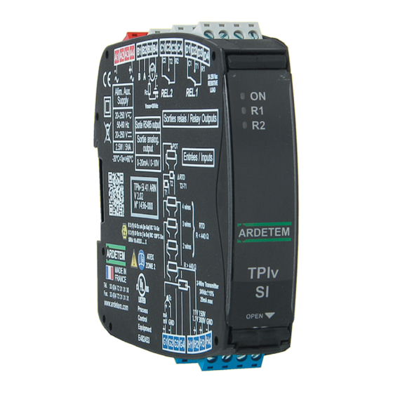
PROGRAMMABLE SIGNAL CONDITIONERS
ÉTUDES ET RÉALISATIONS
ÉLECTRONIQUES / INSTRUMENTATIONS / AUTOMATISME
TPIv-SI 40/41
Route de Brindas - Parc d'activité d'Arbora - N°2
69510 - Soucieu en Jarrest
FRANCE
Tél. 04 72 31 31 30 - Fax 04 72 31 31 31
version 02.x
Tel. Intern. 33 4 72 31 31 30 - Fax Intern. 33 4 72 31 31 31
LCD µconsole
Software SlimSET
User handbook
http: //www.ardetem.com - e-mail: info@ardetem.com
Advertisement

Summary of Contents for ARDETEM TPIv-Sl 40
- Page 1 Tél. 04 72 31 31 30 - Fax 04 72 31 31 31 version 02.x Tel. Intern. 33 4 72 31 31 30 - Fax Intern. 33 4 72 31 31 31 LCD µconsole Software SlimSET User handbook http: //www.ardetem.com - e-mail: info@ardetem.com...
- Page 2 UE CONFORMITY DECLARATION The manufacturer: Summary ARDETEM-SFERE Route de Brindas Parc d’activité d’Arbora n°2 69510 Soucieu en Jarrest UE conformity declaration France 1 . INTRODUCTION declares that the following products: 2 . SPACE REQUIREMENTS Name: Programmable signal conditioners Type: TPIv-SI 40/41 3 .
- Page 3 1. INTRODUCTION The instrument may be connected to dangerous electrical voltages. It must be mounted, connected and implemented respecting The series TPIv-SI offers intrinsic safety inputs. They are associated equipment, to be placed in safe area or area 2 (presence of an the current specific regulations, by a qualified technician, trai- explosive atmosphere accidentally in case of misoperation or of short duration).
- Page 4 Features of the inputs - Relay output R: 2 relays - Mode setpoint or mode window. TPIv-SI Recording of the alarms. Types of Measure range Permanent Intrinsic Input INPUTS adjustable from: overload error impedance Time delay and hysteresis adjustable on each setpoint. Alarm messages.
- Page 5 Power supply: Types of Dielectric OUTPUTS Max. operating range Power draw withstanding 2.5 W max. 20-250 V & 20-250 V 3.0KV-50Hz-1min. 5 VA max. Measure: • Standard sampling time: 100 ms • Common mode rejection rate: 130 dB Serial mode rejection rate: 70 dB 50/60 Hz •...
- Page 6 3. CONNECTINGS Housing: • Self-extinguishing case of black UL 94VO PA66 • Mounting in switchbox: latching on symmetrical DIN rail. SUPPLY INPUTS • Removable terminal blocks for screwed connections (2.5mm², flexible or rigid) • Screw thread M3 Max. tightnening torque: 0.5Nm / 4.5in.lbs 270V Min.
- Page 7 It also allows the teleloading of a programming file to other products of the ARDETEM range. When installed in the hazardous or non-hazardous area, the equipment shall...
- Page 8 Measure screen Unlocking of the keyboard Description Locked keyboard symbole. After 30 sec of inactivity of the keyboard in measure mode, it will be blocked Tactile screen. Press Display of the measure, of the error messages in order to prevent any the measure screen for (eg.: sensor break, scale overrange etc.) or the unintentional pressing.
- Page 9 Moving through the list menus: Entering of a value: Eg.: CODE CODE CODE READ READ READ 0000 0000 2000 INPUT INPUT INPUT DISPLAY DISPLAY DISPLAY MODIF VALID VALID CONF ADV CONF ADV CONF ADV OUTPUT OUTPUT OUTPUT Press RELAYS RELAYS RELAYS MODIF to Use the...
- Page 10 MEASURE SCREEN DIR.FCT MIN MAX Menu of the functions with direct 120.3 MES DIR access see page 13 Press the screen in measure mode to CLR ALR DIAG access the menu of the direct functions PROG REL FILE 1 ADJUST or the display of the details of the lat- BRIGHT 4.000mA...
- Page 11 MAIN READ CFG CODE PROGRAM SET CODE 0000 SIMULAT µ MODIF CON.MEM FUNCTION LANGUAGE SENS.KEY ABOUT if code DISABLE in MANUAL menu SET CODE...
- Page 12 MAIN if access blocked by code READ CFG SIMUL PROGRAM SENSOR CODE SIMUL SET CODE 000.0 SIMUL SIMULAT 0000 SENSOR menu simulation µ (unit) INFO CON.MEM DISPLAY MODIF SENSOR FUNCTION 000.0 OUTPUT MODIF (unit) LANGUAGE SENS.KEY DISPLAY 000.0 ABOUT (unit) MANUAL Enter the OUT1...
- Page 13 Reading of the configuration file stored MENU inside the µconsole memory (same orga- nigramme as for the instrument). INPUT MAIN DISPLAY Note (A) if access blocked by code READ CFG CONF ADV PROGRAM OUTPUT μ CONS CODE SET CODE RELAYS MEMORY SIMULAT RS485...
- Page 14 menu MEASURE SCREEN DIR.FCT DIR.FCT MIN : MIN MAX 0000 120.3 MES DIR MAX : CLR ALR 0000 PROG REL Functions with direct access FILE 1 (unit) ADJUST 4.000mA BRIGHT Press the key CLR MIN MAX To simplify the use, some functions can be accessed in LIGHT to delete the recorded min MIN MAX...
- Page 16 menu INPUT menu programming (or reading) CURRENT INPUT PROG of the input 0-20mA INPUT CURRENT 4-20mA DISPLAY VOLTAGE -/+ 20mA CONF ADV TEMPERA OUTPUT RESISTOR OTHER SC RELAYS POTENTIO RS485 other current down SAFETY see note (C) and up scale SET CONS CURRENT DS.INP...
- Page 18 menu No display scale (the output parameters will be programmed in physical DISPLAY PHYSICAL PROG magnitude according to the input type (V, mA, Ω etc.). DISPLAY DISPLAY INPUT PHY DISP DISPLAY PHY UNIT Menu if PHY CONF ADV D.POINT menu programming (or DISP = YES OUTPUT DS DISP...
- Page 19 transfer function menu CONF ADV ADVANCE ADVANCE SPECIAL PROG NB PTS CONFIG CONFIG LINEAR INPUT DISPLAY TRANSFER LINEAR NB PTS menu programming (or reading) CONF ADV MODIF CUT OFF LIN SPE ABSCISSE of the advanced functions OUTPUT ROOT ORDINATE FILTER RELAYS RS485 SAFETY...
- Page 20 TRANSFER LINEAR : Linear function ROOT : extraction of the square root √ of the measure brought back in % of the programmed measure range. Eg.: Input 4-20mA => 12mA gives 0.707 (√0,5) The function square root tends to amplify the input signal background noise when getting near zero.
- Page 21 menu menu programming (or reading) of the analog output (if option present) OUTPUT other scale PROG OUTPUT 1 OUTPUT 1 DS.OUT FS.OUT INPUT 0-20mA DS OUT 0000 0000 DISPLAY 4-20mA FS OUT mA or V mA or V OUTPUT 1 CONF ADV 20-0mA MODIF...
- Page 22 menu RELAYS ALARM 1 ALARM 1 PROG RELAYS ACTIV Relay not active M.ACTIV INPUT RELAY 1 FCT MODE Programming of DISPLAY RELAY 2 DISABLE SET SPT1 the next relay CONF ADV ACTIVATE SET SPT2 menu programming (or reading) of the OUTPUT Menu present HYSTERES...
- Page 23 ALARM 1 M.ACTIV FCT MODE Status of the LED ALARM 1 SET SPT1 when the relay coil is SET SPT2 HYSTERES supplied LED OFF DELAY AL LED LED ON MEMO AL MESSAGE ALARM 1 M.ACTIV FCT MODE SET SPT1 SET SPT2 HYSTERES DELAY AL LED...
- Page 24 • Mode setpoint D E L A Y x • Time delay on the alarm Setting of the delay from 0 to 999,9 sec. DOUB DEL: delay on switching on alarm and off alarm setpoint setpoint SIMP DEL: delay only on switching on alarm SPI.X SPI.X Legend:...
- Page 25 menu RS485 PROG SLAVE Slave number: between 1 and 255 RS485 INPUT SLAVE DISPLAY BAUD RAT CONF ADV PARITY MODIF OUTPUT TX RANK menu programming (or reading) of the RELAYS DELAY RS485 RS485 output (if option present) SAFETY SET CONS EXIT RS485 BAUD RAT...
- Page 26 menu PROG RUPTURE Only if input mV/TC SAFETY DETECT SAFETY INPUT DETECT RUPTURE ENABLE Disconnection of the sensor DISPLAY RELAY 1 break detection DIAGNOSI DISABLE CONF ADV RELAY 2 menu programming (or reading) of the OUTPUT 1 OUTPUT CHECK MA safety functions RELAYS OUTPUT 2...
- Page 27 SAFETY SAFETIES : • Sensor break The sensor break can be detected on the inputs mV, Tc, Pt100, Ni100, resistance (<400Ω) and current if the down and up scale <3.5mA. OPEN On the µconsole: the message appears On the converter: The LED ON blinks (approx. 4Hz) Disconnection of the sensor break detection: (if input mV or temperature) The sensor break detection can be disconnected in order not to disturb some calibrators which may be sensitive to the rupture detection current.
- Page 28 menu Setting of the BRIGHT LIGHT PROG µconsole contrast and SET CONS µ CONS INPUT LEVEL 1 LEVEL 1 brightness DISPLAY LEVEL 2 LEVEL 2 BRIGHT CONF ADV LIGHT menu programming (or reading) of the OUTPUT LEVEL 10 LEVEL 10 SENS.KEY RELAYS functions concerning the µconsole...
- Page 29 µ CONS Mode idle of the µconsole BRIGHT after 10 min. of inactivity IDLE LIGHT MODE SENS.KEY IDLE OFF LANGUAGE IDLE ON IDLE MOD TOUCH F1 TOUCH F2 PROG INPUT µ CONS DISPLAY KEY Fx CONF ADV BRIGHT OUTPUT MIN MAX LIGHT RELAYS DIR MES...
- Page 30 menu PROG PROG INPUT INPUT DISPLAY DISPLAY CONF ADV CONF ADV Entering of the name given OUTPUT OUTPUT to the configuration (8 cha- RELAYS RELAYS racters max.) displayed on RS485 RS485 the measure screen SAFETY SAFETY FILE 1 SET CONS SET CONS MODIF EXIT...
- Page 31 7. ANNEXE: MODBUS 5. ERROR MESSAGES Upper or lower electrical Measure in overrange 7.1 Table of the Modbus addresses 2000 ---- overstepping of the input Word address Description Sensor break OPEN Displayable value overload Measure of the sensor primary decimal point/unit Self-diagnosis error Value set out of range ERR1...
- Page 32 Table of units 7.2 Description of the born Modbus functions: Code Unit Code Unit Code Unit Code Unit Code Unit Reading of N words: Function n°3 023 MVARh 100 °C 122 mm/s 144 mV DC 024 GVARh 101 °F 001 V 123 cm/s 145 V DC 025 Hz...
- Page 33 Writing of 1 word: Function N°6: Measure = byte 3 x 256 3 + byte 4 x 256 2 + byte 1 x 256 + byte 2 Request sequence: = 0 x 256 3 + 0 x 256 2 + 19 x 256 + 136 Value of = 5000...
- Page 34 7.4 CRC 16 calculation algorythm : FFFF → CRC CRC ⊕ BYTE→ CRC n = 0 shifting by 1 bit to the right of CRC carry CRC ⊕ poly → CRC n = n + 1 n > 7 next byte end of sequence Note 1: ⊕...
Need help?
Do you have a question about the TPIv-Sl 40 and is the answer not in the manual?
Questions and answers