
Summary of Contents for RAVEO RM42A
- Page 1 RM42A Digital Stepper Drive User Manual User Manual RM42A 2-Phase Digital Stepper Drive Hardware Version 2.0 Manual Revision 1.0...
-
Page 2: Table Of Contents
RM42A Digital Stepper Drive User Manual Table of Contents 1. Features ..................................1 2. Specifications ................................. 1 2.1 Electrical Specifications ............................1 2.2 Environment ................................1 2.3 Mechanical Specifications ............................ 2 2.4 Elimination of Heat ............................... 2 3. Connection Pin Assignments and LED Indication ..................... 2 3.1 P1 - Control Connector ............................ -
Page 3: Features
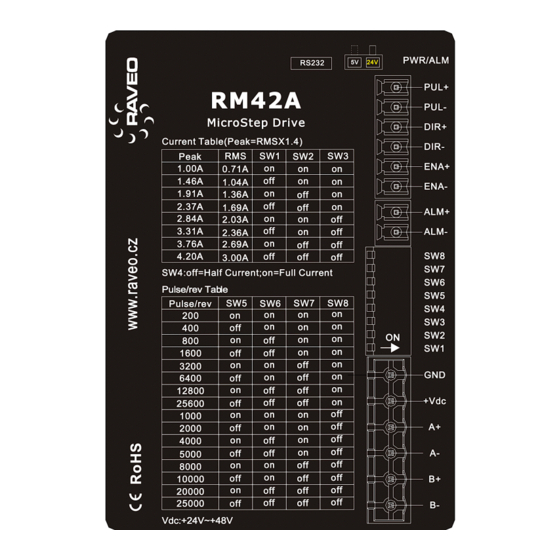
RM42A Digital Stepper Drive User Manual 1. Features l Step & direction (PUL/DIR) control l Input voltage 18-50VDC (recommended 24-48VDC) l 200 KHz max pulse input frequency l 16 microstep resolutions of 200-51,200 via DIP switches l 8 output current settings of 1.0-4.2A via DIP Switches... -
Page 4: Mechanical Specifications
Connectors, DIP switches, and LED locations The RM42A has three connector blocks P1&P2&P3 (see above picture). P1 is for control signals connections, and P2 is for output signals connections, P3 is for power and motor connections. The following tables are brief descriptions of the three connectors. -
Page 5: P1 - Control Connector
Motor Phase B connections. Connect motor B+ wire to B+ Pin; motor B- wire to B- Warning Warning: Don’t plug or unplug the P1 & P2&P3 terminal block to avoid drive damage or injury when RM42A is powered on. 3.4 P4 - RS232 Tuning Port The P4 connector in Figure 2 is a RS232 communication port for PC connection. -
Page 6: Led Light Indication
3.5 LED Light Indication There are two LED lights for RM42A. The GREEN one is the power indicator which will be always on generally. The RED one is a protection indicator which will flash 1-2 times in a 3-second period, when protection enabled for a RM42A. -
Page 7: Motor Connection
6. Power Supply Selection The RM42A can power medium and large size stepping motors (frame size from NEMA 11 to 24). To get good driving performances, it is important to select supply voltage and output current properly. Generally speaking, supply voltage determines the high speed performance of the motor, while output current determines the output torque of the driven motor (particularly at lower speed). -
Page 8: Selecting Supply Voltage
7. DIP Switch Configurations The RM42A has one 8-bit DIP switch and one 1-bit selector. The first 8-bit is used to configure settings of micro step resolution, output current, motor standstill current, pulse type and smoothing time as shown below. -
Page 9: Output Current Configurations
The current automatically reduced to 50% of the selected dynamic current 0.4 second after the last pulse. 7.3 Automatic Motor Matching & Self Configuration When powered on a RM42A will automatically configure itself with the best settings to match the driven stepper motor for optimal performance. No action is needed. -
Page 10: Typical Connection
RM42A Digital Stepper Drive User Manual 9. Typical Connection A complete stepping system should include stepping motor, stepping drive, power supply and controller (pulse generator). A typical connection is shown as below. Controller Drive PUL+ Step PUL- DIR+ Direction DIR-... -
Page 11: Protection Functions
RM42A Digital Stepper Drive User Manual 11. Protection Functions To improve reliability, the drive incorporates some built-in protections features. Time(s) of Priority Sequence wave of red LED Description Blink Over-current protection activated when peak current exceeds the limit. Over-voltage protection activated when drive working voltage is greater than 60VDC Reserved. -
Page 12: Troubleshooting
RM42A Digital Stepper Drive User Manual 12. Troubleshooting In the event that your drive doesn’t operate properly, the first step is to identify whether the problem is electrical or mechanical in nature. The next step is to isolate the system component that is causing the problem. As part of this process you may have to disconnect the individual components that make up your system and verify that they operate independently. -
Page 13: Warranty
RM42A Digital Stepper Drive User Manual 13. Warranty Twelve Month Warranty Exclusions The above warranty does not extend to any product damaged by reasons of improper or inadequate handlings by customer, improper or inadequate customer wirings, unauthorized modification or misuse, or operation beyond the electrical specifications of the product and/or operation beyond environmental specifications for the product.
Need help?
Do you have a question about the RM42A and is the answer not in the manual?
Questions and answers