
Summary of Contents for Divio NRP1482
- Page 1 Video Intelligent Surveillance NRP1482 User Manual Note: The manual is subject to change without notice diviotec.com...
-
Page 2: Table Of Contents
SATA Power Connector .............. 16 Hardware Specifications ............... 2 Audio Connectors ..............17 Power SW Connector ..............17 Knowing Your NRP1482 Series .............. 3 COM Port Connector ..............18 Front Panel ..................3 NRP1482 Rear Panel ................. 4 Debug Port Connector ............... 18 Mechanical Dimensions................. - Page 3 Preface Chapter 4: BIOS Setup About BIOS Setup ................. 43 When to Configure the BIOS ............43 Default Configuration ..............44 Entering Setup ................44 Legends ..................44 BIOS Setup Utility ................. 46 Main ..................46 Advanced ................. 47 Chipset ..................56 Security ..................
-
Page 4: Chapter 1: Product Introduction
Chapter 1: Product Introduction 1: P HAPTER RODUCT NTRODUCTION Key Features Overview ▪ Intel Celeron J6412, Quad Core 2.0GHz ▪ Max. 32GB DDR4 supported ▪ Dual display of HDMI and DVI-I ▪ 1 x 3.5” SATA HDD ▪ 1 x 2.5” SATA HDD or SSD/1 x M.2 2242 Key B SATA III (select either one) ▪... -
Page 5: Hardware Specifications
Chapter 1: Product Introduction Hardware Specifications CPU Support ▪ Intel 8 Gen Intel Celeron J6412, Quad Core, 2.0GHz base frequency, Storage ® ® 2.6 GHz burst frequency (compatible with other Intel 8 Gen Intel Atom ▪ 1 x 3.5” SATA HDD ®... -
Page 6: Knowing Your Nrp1482 Series
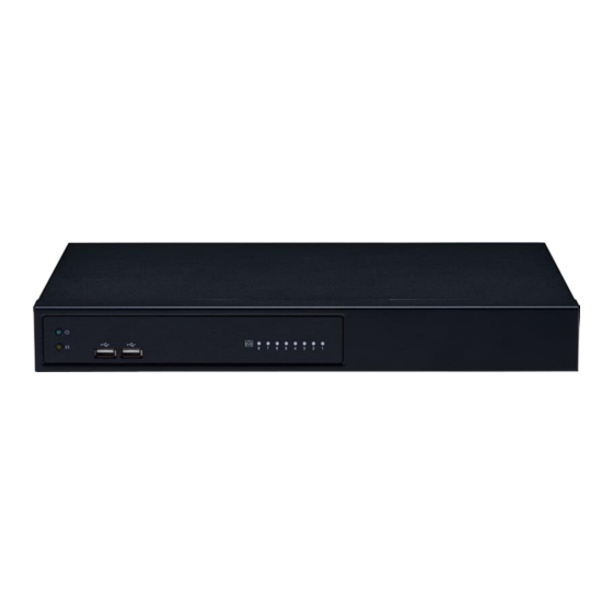
Chapter 1: Product Introduction Knowing Your NRP1482 Series LED Indicators Indicates the power status of the system. Front Panel Indicates the status of the hard drive. Dual USB Ports Used to connect USB 2.0 devices. PoE LAN LED Indicators Indicates the status of the LAN ports. -
Page 7: Nrp1482 Rear Panel
Chapter 1: Product Introduction NRP1482 Rear Panel 1x COM (RS232/RS485) Port (BIOS Support) Supports RS232 and RS485 compatible serial devices. DVI-I Used to connect a digital LCD panel. HDMI Used to connect a high-definition display. 1.0 GbE RJ45 8x PoE LAN Ports RJ45 Connector 1.0 GbE RJ45/2.5 GbE RJ45... -
Page 8: Mechanical Dimensions
Chapter 1: Product Introduction Mechanical Dimensions Rackmount Model 366.00 192.80 224.50 3.00 28.70 360.00 16.00 44.00 6.00 6.00 465.00 482.80... -
Page 9: Mechanical Dimensions
Chapter 1: Product Introduction Mechanical Dimensions Desktop Model 126.00 224.50 67.50 360.00 360.00 44.00 49.00 287.80 36.10... -
Page 10: Mechanical Dimensions
Chapter 1: Product Introduction Mechanical Dimensions Wallmount Model 60.00 160.00 8.20 60.00 68.50 50.50 373.80 387.80 360.00 44. 00 50.0... -
Page 11: Chapter 2: Jumpers And Connectors
UMPERS AND ONNECTORS This chapter describes how to set the jumpers and connectors on the dry environments. A grounding strap is warranted whenever danger of NRP1482 series motherboard. static electricity exists. Before You Begin Precautions ▪ Ensure you have a stable, clean working environment. Dust and dirt can Computer components and electronic circuit boards can be damaged by get into components and cause a malfunction. -
Page 12: Jumper Settings
Chapter 2: Jumpers and Connectors Jumper Settings A jumper is the simplest kind of electric switch. It consists of two metal pins and a cap. When setting the jumpers, ensure that the jumper caps are placed on the correct pins. When the jumper cap is placed on both pins, the jumper is short. -
Page 13: Locations Of The Jumpers And Connectors
Chapter 2: Jumpers and Connectors Locations of the Jumpers and Connectors The figure below shows the location of the jumpers and connectors. 30 29 32 31 FAN2 CN4 CN1 CN3 CN2 145 143 DIMM1 PWR_SW1 146 144 145 143 CN11 DIMM2 2 10 146 144... -
Page 14: Jumpers
Chapter 2: Jumpers and Connectors Jumpers Clear CMOS Connector type: 1x3 3-pin header Connector location: JP1 Settings Normal Clear CMOS 1-2 On: default... -
Page 15: Connector Pin Definitions
Chapter 2: Jumpers and Connectors Connector Pin Definitions PoE LAN 8 Ports RJ45 Connector Connector type: Phone Jack RJ45 2x4 Port PoE 54V Power-in Connector (Outside) Connector location: CON5 Connector type: 2x2 4-pin header Connector location: CON6 Definition Definition 54V-in 54V-in... -
Page 16: Gpio Connector
Chapter 2: Jumpers and Connectors GPIO Connector Connector type: 2x5 10-pin header Connector location: CN8 10 9 Definition Definition Definition Definition 5.0V 5.0V GPIO84 GPIO80 GPIO84 GPIO85 GPIO86 GPIO81 GPIO85 GPIO87 GPIO82 GPIO86 GPIO80 GPIO81 GPIO83 GPIO87 GPIO82 GPIO83... -
Page 17: System Fan
Chapter 2: Jumpers and Connectors System Fan USB2.0 Connector Connector type: 1x4 4-pin header Connector type: 2x5 10-pin header Connector location: FAN2 Connector location: CN6 10 9 Definition Definition Definition Definition +12V V5P0_USB2_HDR V5P0_USB2_HDR SYS2_FAN_TACO SYS2_FAN_PWM USB2_4_DN_CM USB2_5_DN_CM USB2_4_DP_CM USB2_5_DP_CM... -
Page 18: Hdd/Pwr Led Wire
Chapter 2: Jumpers and Connectors HDD/PWR LED Wire SATA Connector Connector type: 1x4 4-pin header Connector type: 1x4 4-pin header Connector location: CN11 Connector location: CN1 Definition Definition Definition Definition LED_PWR_PU LED_PWR_LOGIC_N SATA_CON1_TXP LED_HDD_LOGIC_N LED_HDD_PU SATA_CON1_TXN SATA_CON1_RXN SATA_CON1_RXP... -
Page 19: Sata Connector
Chapter 2: Jumpers and Connectors SATA Connector SATA Power Connector Connector type: 1x4 4-pin header Connector type: 1x4 4-pin header Connector location: CN4 Connector location: CN2, CN3 Definition Definition Definition Definition SATA_CON2_TXP V12P0_SATA SATA_CON2_TXN V5P0_SATA SATA_CON2_RXN SATA_CON2_RXP... -
Page 20: Audio Connectors
Chapter 2: Jumpers and Connectors Audio Connectors Power SW Connector Connector location: AUDIO1 Connector type: 1x2 2-pin header Connector location: PWR_SW1 Line-in Line-out Mic-in Definition Definition PWRBTN_N... -
Page 21: Com Port Connector
Chapter 2: Jumpers and Connectors COM Port Connector Debug Port Connector Connector type: 1x10 10-pin header Connector type: 1x10 10-pin header Connector location: CN9 Connector location: ESPI_DB1 Definition Definition Definition Definition SP2_DCD_N SP2_RXD PMC_PLTRST_N SP2_TXD SP2_DTR_N ESPI_CLK ESPI_CS0_N SP2_DSR_N ESPI_IO3 ESPI_IO2 SP2_RTS_N SP2_CTS_N... -
Page 22: Lan1 Connector And Usb 3.0 Ports
Chapter 2: Jumpers and Connectors LAN1 Connector and USB 3.0 Ports LAN2 Connector and USB 3.0 Ports Connector type: RJ45 port with LEDs Connector type: RJ45 port with LEDs Dual USB3.0 ports Dual USB3.0 ports Connector location: CON3 Connector location: CON4 Status Status Yellow... -
Page 23: Spi Bios Update Connector
Chapter 2: Jumpers and Connectors SPI BIOS Update Connector HDMI Connector Connector type: 2x4 8-pin header Connector type: HDMI Connector location: JP3 Connector location: CON2 Definition Definition Definition Definition V3P3_V1P8_SPI SPI0_CS_N HDMI_TX2_DP_CM SPI0_HOLD_N SPI0_MISO_N HDMI_TX2_DN_CM HDMI_TX1_DP_CM FSPI_CLK_SPI0 SPI0_WP_N HDMI_TX1_DN_CM SPI0_MOSI_N HDMI_TX0_DP_CM HDMI_TX0_DN_CM HDMI_CLK_DP_CM... -
Page 24: Dvi-I And Rs485 Connector
Chapter 2: Jumpers and Connectors DVI-I and RS485 Connector Connector location: CON1 C1 C2 C3 C4 Definition Definition Definition Definition DVI_D2_N DVI_D2_P SP1_R1_N VGA_RED_C VGA_GREEN_C VGA_BLUE_C DVI_DDC_SCL VGA_HSYNC_C VGA_GND DVI_DDC_SDA VGA_VSYNC_C DVI_D1_N DVI_D1_P +DVI_5V DVI_HPD_C DVI_D0_N DVI_D0_P VGA_DDCCLK_C VGA_DDCDATA_C DVI_CK_P DVI_CK_N SP1_DCD_N SP1_RXD... -
Page 25: Poe 8 Ports Lan Led Connector
Chapter 2: Jumpers and Connectors POE 8 Ports LAN LED Connector Connector type: 2x10 20-pin header Connector location: CN7 Definition Definition V3P3_IP403 V3P3_IP403 P1LINK_ACT POE_P1_STATE P2LINK_ACT POE_P2_STATE P3LINK_ACT POE_P3_STATE P4LINK_ACT POE_P4_STATE P5LINK_ACT POE_P5_STATE P6LINK_ACT POE_P6_STATE P7LINK_ACT POE_P7_STATE P8LINK_ACT POE_P8_STATE V3P3_IP403 V3P3_IP403... -
Page 26: M.2 B Key Connector
Chapter 2: Jumpers and Connectors M.2 B Key Connector Connector location: CN6 Definition Definition SATA_DEVSLP0 M2_SATA_RP M2_SATA_RN Definition Definition V3P3A_M2E V3P3A_M2E M2_SATA_TN M2_SATA_TP M2_SATA_LED_N CONNECTOR KEY MFG_DATA CONNECTOR KEY CONNECTOR KEY MFG_CLK CONNECTOR KEY CONNECTOR KEY CONNECTOR KEY CONNECTOR KEY CONNECTOR KEY M2E_SUSCLK M2E_SEL_N... -
Page 27: Poe Switch Action Guidance
Chapter 2: Jumpers and Connectors PoE Switch Action Guidance PoE Switch Deployment 8ch PoE ports 10/100 Mbps, 802.3af/at compliance with a total of 120W 1. AF Mode max (PSE) Port 1, 2, 3, 4, 5, 6, 7, 8 ▪ 802.3af support 8port @ 15W ▪... - Page 28 Chapter 2: Jumpers and Connectors Port 5, 6, 7, 8 3AT + 2AF 3. AF/AT Multi-mode 1AT + 6AF 2AT + 4AF...
-
Page 29: Block Diagram
Chapter 2: Jumpers and Connectors Block Diagram DDR4 CH-A ** Intel dropped HBR3 support 3200 MT/s; 51GB/s (MAX) SO-DIMM Module DC Jack DDR4 CH-B Power Supply DDI-0 (HBR2) CH7157A-BFI 54V 12V 54V Input 3200 MT/s; 51GB/s (MAX) DVI-I DDI-1 (HBR2) PTN3360DBS Elkhart Lake Power Supply... -
Page 30: Chapter 3: System Setup
Chapter 3: System Setup 3: S HAPTER YSTEM ETUP Removing the Chassis Cover Prior to removing the chassis cover, make sure the unit’s power is off and disconnected from the power sources to prevent electric shock or system damage. 1. Remove the 11 screws on the system’s top cover. (Out of the 11 screws, Short screws there are 6 long screws and 5 short screws.) Long screws... -
Page 31: Installing The 3.5" Hdd
Chapter 3: System Setup Installing the 3.5” HDD 1. Remove the HDD bracket. - Page 32 Chapter 3: System Setup 2. Set 3.5” HDD into the HDD bracket. (Use #6-32 type screw) #6-32 screw x4 (3.5” HDD lock on bracket)
- Page 33 Chapter 3: System Setup 3. Plug in the HDD SATA cable and SATA power cable, install the HDD set into the system. Note: HDD SATA cable should be installed at CN4 of the mainboard. SATA power cable should be installed at CN3 of the mainboard.
- Page 34 Chapter 3: System Setup 4. Lock the screw.
- Page 35 Chapter 3: System Setup 5. Tightening Cable Guidance For 3.5” HDD Complete!
- Page 36 Chapter 3: System Setup 6. Complete!
-
Page 37: Installing The 2.5" Ssd/Hdd
Chapter 3: System Setup Installing the 2.5” SSD/HDD 1. Remove the HDD bracket. Note: The SATA port CN1 and M.2 slot cannot be used simultaneously. - Page 38 Chapter 3: System Setup 2. Set 2.5” SSD/HDD into the HDD bracket. (Use M3 type screw) M3 screw x4 (2.5” HDD lock on bracket)
- Page 39 Chapter 3: System Setup 3. Plug in the SATA cable and SATA power cable, install the SSD/HDD set 4. Lock the screw. into the system. Note: SATA cable should be installed at CN1 of the mainboard. SATA power cable should be installed at CN2 of the mainboard.
-
Page 40: Tightening Cable Guidance For 2.5" Ssd/Hdd
Chapter 3: System Setup 5. Tightening Cable Guidance For 2.5” SSD/HDD Complete! - Page 41 Chapter 3: System Setup 6. Complete!
-
Page 42: Installing M.2 Ssd
Chapter 3: System Setup Installing M.2 SSD 2. Insert the M.2 SSD into the M.2 slot at a 45 degree angle until the 1. First, remove the screw on the board. gold -plated connector on the edge of the module completely dissapears inside the slot. - Page 43 Chapter 3: System Setup 3. With the module fully inserted, tighten a screw into the mounting hole 4. Complete! on the module to secure it. M.2 2242 B-key...
-
Page 44: Installing Memory So-Dimm (Use Ddr4 So-Dimm)
Chapter 3: System Setup Installing Memory SO-DIMM (Use DDR4 SO-DIMM) 1. Locate the DIMM memory sockets. 2. Release the locks on the DIMM memory sockets. Insert the modules into the sockets at a 90 degree angle. Apply firm even pressure to each end of the modules until they slip into the sockets. - Page 45 Chapter 3: System Setup 2. Release the locks on the second DIMM memory sockets. Insert the other 4. Complete! module into the sockets also at a 90 degree angle. Apply firm even pressure to each end of the modules until they slip into the sockets.
-
Page 46: Chapter 4: Bios Setup
HAPTER ETUP This chapter describes how to use the BIOS setup program for the NRP1482 The settings made in the setup program affect how the computer performs. series. The BIOS screens provided in this chapter are for reference only and It is important, therefore, first to try to understand all the setup options, and may change if the BIOS is updated in the future. -
Page 47: Default Configuration
Chapter 4: BIOS Setup Default Configuration Legends Most of the configuration settings are either predefined according to Function the Load Optimal Defaults settings which are stored in the BIOS or are automatically detected and configured without requiring any actions. There Moves the highlight left or right to select a menu. - Page 48 Chapter 4: BIOS Setup Scroll Bar When a scroll bar appears to the right of the setup screen, it indicates that there are more available fields not shown on the screen. Use the up and down arrow keys to scroll through all the available fields. Submenu When “”...
-
Page 49: Bios Setup Utility
Advanced Chipset Security Boot Save & Exit ▲ BIOS Information BIOS Vendor American Megatrends Product Name NRP1482 Series RN14- BIOS Version 005 x64 08/18/2021 Build Date and Time 15:14:20 Processor Information Intel(R) Celeron(R) J6412 @ 2.00GHz 0x90661 Microcode Revision Stepping... -
Page 50: Advanced
Chapter 4: BIOS Setup Advanced CPU Configuration This section is used to view CPU status and configure CPU parameters. The Advanced menu allows you to configure your system for basic operation. Some entries are defaults required by the system board, while others, if Aptio Setup - AMI enabled, will improve the performance of your system or let you set some Advanced... - Page 51 Chapter 4: BIOS Setup Power & Performance CPU - Power Management Control This section is used to configure the power management features of the CPU. Aptio Setup - AMI Advanced Aptio Setup - AMI CPU - Power Management Control Select the performance state Advanced that the BIOS will set starting from reset vector.
- Page 52 Chapter 4: BIOS Setup ® Intel Speed Shift Technology Enables or disables Intel Speed Shift Technology support. Enabling it will expose the CPPC v2 interface to allow hardware controlled P-states. C states Enables or disables CPU C states support for power saving.
- Page 53 Chapter 4: BIOS Setup Trusted Computing Pending operation Scheduling an operation for the security device. This section is used to configure Trusted Platform Module (TPM) settings. Note: Your computer will reboot during restart in order to change state of security device. Aptio Setup - AMI Advanced Platform Hierarchy...
- Page 54 Chapter 4: BIOS Setup NCT5525D Super IO Configuration Serial Port 1 Configuration This section is used to configure the serial port. This section is used to configure serial port 1. Aptio Setup - AMI Aptio Setup - AMI Advanced Advanced NCT5525D Super IO Configuration Set Parameters of Serial Port Serial Port 1 Configuration...
- Page 55 Chapter 4: BIOS Setup Hardware Monitor System Fan Setting This section is used to monitor hardware such as temperature, fan speed This section is used to configure system fan settings. and voltages. Aptio Setup - AMI Aptio Setup - AMI Advanced Advanced PC Health Status...
- Page 56 Chapter 4: BIOS Setup System Fan Setting Temperature 1 to Temperature 4 Configures the temperature setting. Aptio Setup - AMI FD/RPM 1 to FD/RPM 4 Advanced The value of Fan Duty/RPM when temperature is T1 to T4. System Fan Setting Fan control mode select System Fan mode [SMART FAN IV]...
- Page 57 Chapter 4: BIOS Setup USB Configuration USB Mass Storage Driver Support Enables or disables USB Mass Storage Driver Support. This section is used to configure USB parameters. USB Transfer Time-out Aptio Setup - AMI The time-out value for control, bulk, and interrupt transfers. Advanced Device Reset Time-Out USB Configuration...
- Page 58 Chapter 4: BIOS Setup Network Stack SDIO Configuration This section is used to configure the network stack. This section is used to configure the SDIO access mode. Aptio Setup - AMI Aptio Setup - AMI Advanced Advanced ▲ SDIO Configuration Auto Option: Access SD device Network Stack [Disabled]...
-
Page 59: Chipset
Chapter 4: BIOS Setup Chipset System Agent (SA) Configuration This section gives you functions to configure the system based on the Aptio Setup - AMI specific features of the chipset. The chipset manages bus speeds and access Chipset to system memory resources. Memory Configuration Parameters System Agent (SA) Configuration Aptio Setup - AMI... - Page 60 Chapter 4: BIOS Setup Memory Configuration Graphics Configuration Aptio Setup - AMI Aptio Setup - AMI Chipset Chipset Memory Configuration Safe Mode enable support. Graphics Configuration Graphics turbo IMON current Option will be used for values supported (14-31) changes/WAS that may affect an Memory RC Version 0.0.4.104 Graphics Turbo IMON Current...
- Page 61 Chapter 4: BIOS Setup GTT Size PCH-IO Configuration Configures the GTT memory size. This section is used to configure PCH-IO configuration. Aperture Size Aptio Setup - AMI Configures the Aperture size. Main Advanced Chipset Security Boot Save & Exit Note: above 4MB MMIO BIOS assignment is automatically enabled when PCH-IO Configuration SATA Device Options Settings selecting 2048MB aperture.
- Page 62 Chapter 4: BIOS Setup SATA Configuration SATA Ports Multiplier Enables or disables ports multiplier. This section is used to configure the SATA device option settings. SATA Test Mode Aptio Setup - AMI Enables or disables test mode. Main Advanced Chipset Security Boot Save &...
- Page 63 Chapter 4: BIOS Setup USB Configuration USB PDO Programming Aptio Setup - AMI Select ‘Enabled’ if port disable override functionality is used. Main Advanced Chipset Security Boot Save & Exit USB Overcurrent USB Configuration Option to enable Compliance Mode. Default is to disable Select ‘Disabled’...
-
Page 64: Security
Chapter 4: BIOS Setup PCH-IO Configuration Security This section is used to configure PCH-IO configuration. Aptio Setup - AMI Main Advanced Chipset Security Boot Save & Exit Aptio Setup - AMI Main Advanced Chipset Security Boot Save & Exit Password Description Set Administrator Password PCH-IO Configuration Specify what state to go to when... -
Page 65: Secure Boot
Chapter 4: BIOS Setup Secure Boot Boot Aptio Setup - AMI Aptio Setup - AMI Main Advanced Chipset Security Boot Save & Exit Save & Exit Main Advanced Chipset Security Boot System Mode Setup Secure Boot feature is Active Boot Configuration Select the keyboard NumLock if Secure Boot is Enabled. - Page 66 Chapter 4: BIOS Setup Save & Exit Aptio Setup - AMI Main Advanced Chipset Security Boot Save & Exit Save Changes and Reset Exit the system after saving the changes. Discard Changes and Reset Restore Defaults →←: Select Screen ↑↓: Select Item Enter: Select +/-: Change Opt.
Need help?
Do you have a question about the NRP1482 and is the answer not in the manual?
Questions and answers