Table of Contents
Advertisement
Quick Links
Advertisement
Table of Contents

Summary of Contents for LG RT-29CC25R
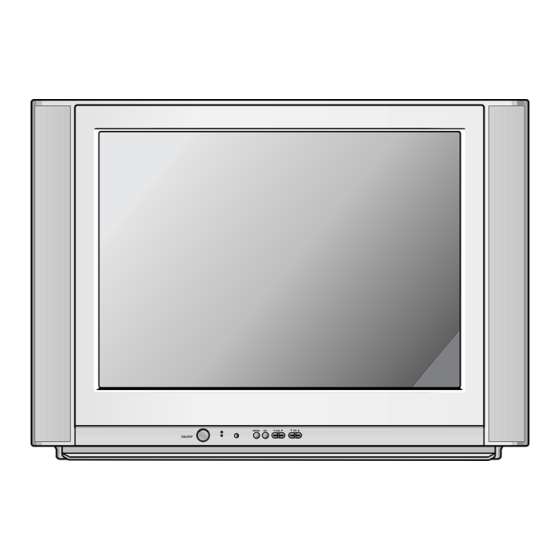
- Page 1 COLOR TV SERVICE MANUAL CHASSIS : MC-049A MODEL:RT-29CC25R/RX MODEL:RT-29CC25VB/VD/VX CAUTION BEFORE SERVICING THE CHASSIS, READ THE SAFETY PRECAUTIONS IN THIS MANUAL. MENU ON/OFF...
-
Page 2: Table Of Contents
CONTENTS Contents ........................2 Safety Precautions....................3 Control Descriptions..................4 Specifications......................7 Adjustment Instructions .................8 T rouble Shooting....................12 Printed circuit board..................16 Block Diagram ......................18 Exploded View....................20 Exploded View Parts List ................21 Replacement Parts List .................22 SVC. Sheet........................- 2 -... -
Page 3: Safety Precautions
SAFETY PRECAUTIONS IMPORT ANT SAFETY NOTICE Many electrical and mechanical parts in this chassis have special safety-related characteristics. These parts are identified by the Schematic Diagram and Replacement Parts List. It is essential that these special safety parts should be replaced with the same components as recommended in this manual to prevent X-RADIATION, Shock, Fire, or other Hazards. -
Page 4: Control Descriptions
DESCRIPTION OF CONTROLS - 4 -... - Page 5 - 5 -...
- Page 6 - 6 -...
-
Page 7: Specifications
P/N of B.O.M 5) Warm up TV set for more than 20min. before the 230V~, 50/60Hz measurement. Test and Inspection Method 1) performance:Follow the Standard of LG TV test 2) Standards of Etc. requirement - Safety: IEC60065 - EMC: EN55020,EN55013 General Specification... -
Page 8: Adjustment Instructions
ADJUSTMENT INSTRUCTIONS 1. Application Object 4. Purity & Convergence adjustment These instructions are applied to all of the color TV, MC-049A. As preparatory operations before CPT Assembling assembling CPT, wind cotton Tape for 2. Notes protecting to CPT NECK and DY, CPT connection parts. - Page 9 (5) Open angle of the two tab of 6 pole magnet by isogonic 2. White balance IIC Parameter angle and accord with vertical line of Red/Blue and Green. Program TWBeng2.0 Program TWBeng2.0 Speed Delay (6) Maintain as angle of (5) and rotate the tab to accord with horizontal line.
- Page 10 N50Hz(PAL) N60Hz(NTSC) Menu Variable range 29” 29” -512~511 -512~511 -512~511 -512~511 32~2047 -256~255 -512~511 <Fig. 2>PAL Digital pattern (EU05CH) -512~511 ANGLE -512~511 (4) VS (Vertical Shift) adjustment: Adjust so that the geometric vertical center line is in accord -512~511 with vertical center line of CPT. UPCOR -512~511 (5) HS(Horizontal Shift) adjustment:...
- Page 11 8-4. OPTION2 Function Option Code Function TSEARCH Without TURBO SEARCH With TURBO SEARCH 200PR 100 PROGRAM SAVE 200 PROGRAM SAVE Without EYE With EYE TX019 8KEY 8KEY 4KEY 4KEY 8-5. OPTION3 Function Option Code Function REMARK SYSTEM ACMS Without ACMS Function With ACMS Function FLOT TXT TOP TXT...
-
Page 12: Trouble Shooting
TROUBLE SHOOTING - 12 -... - Page 13 - 13 -...
- Page 14 - 14 -...
- Page 15 - 15 -...
-
Page 16: Printed Circuit Board
PRINTED CIRCUIT BOARD MAIN - 16 -... - Page 17 SIDE A/V - 17 -...
-
Page 18: Block Diagram
BLOCK DIAGRAM - 18 -... - Page 19 - 19 -...
-
Page 20: Exploded View
EXPLODED VIEW - 20 -... -
Page 21: Exploded View Parts List
BACK COVER ASSEMBLY, RT-29CC20VD(SET) 2PHONE 51SF 3809V00390C BACK COVER ASSEMBLY, RT-29CC20RX 2PHONE 40AF 3809V00390D BACK COVER ASSEMBLY, RT-29CC20VX 2PHONE CKD 3809V00390E BACK COVER ASSEMBLY, RT-29CC25R 2PHONE 40AF 3809V00390F BACK COVER ASSEMBLY, RT-29CC25VD 2PHONE SET 6871VMMT50A PWB(PCB) ASSEMBLY,MAIN MC049A RT-29CC25RX.AHLLKG 6871VMMT50C PWB(PCB) ASSEMBLY,MAIN MC049A RT-29CC25VD.AFLLKF... -
Page 22: Replacement Parts List
REPLACEMENT PARTS LIST For Capacitor & Resistors, the CC, CX, CK, CN : Ceramic RD : Carbon Film charactors at 2nd and 3rd digit CQ : Polyestor RS : Metal Oxide Film in the P/No. means as follows; CE : Electrolytic RN : Metal Film RF : Fusible LOCA. - Page 23 For Capacitor & Resistors, CC, CX, CK, CN : Ceramic RD : Carbon Film the charactors at 2nd and 3rd CQ : Polyestor RS : Metal Oxide Film digit in the P/No. means as CE : Electrolytic RN : Metal Film follows;...
- Page 24 For Capacitor & Resistors, CC, CX, CK, CN : Ceramic RD : Carbon Film the charactors at 2nd and 3rd CQ : Polyestor RS : Metal Oxide Film digit in the P/No. means as CE : Electrolytic RN : Metal Film follows;...
- Page 25 For Capacitor & Resistors, CC, CX, CK, CN : Ceramic RD : Carbon Film the charactors at 2nd and 3rd CQ : Polyestor RS : Metal Oxide Film digit in the P/No. means as CE : Electrolytic RN : Metal Film follows;...
- Page 26 For Capacitor & Resistors, CC, CX, CK, CN : Ceramic RD : Carbon Film the charactors at 2nd and 3rd CQ : Polyestor RS : Metal Oxide Film digit in the P/No. means as CE : Electrolytic RN : Metal Film follows;...
- Page 27 R912 0RD2204A609 2.2M OHM 1/2 W(7.0) 5.00% TA52 0RD2200F609 220 OHM 1/6 W 5.00% TA52 R925 SWITCH SW11 140-315A TACT SKHV17910B LG C&D 12V TACT SKHV17910B LG C&D 12V SW12 140-315A SW13 140-315A TACT SKHV17910B LG C&D 12V SW14 140-315A TACT SKHV17910B LG C&D 12V...
- Page 28 P/NO: 3854VA0146A - S1 2004.4.16...
-
Page 29: Svc. Sheet
SVC. SHEET : 3854V A0146A-S... - Page 30 Oct.,2004 P/NO : 3828VD0194B Printed in Korea...


Need help?
Do you have a question about the RT-29CC25R and is the answer not in the manual?
Questions and answers