Table of Contents
Advertisement
Quick Links
Miller®
OWNER'S MANUAL
IMPORTANT: Read and understand the entire contents of both this
manual and the power source manual used with this unit, with special
emphasis on the safety material throughout both manuals, before in-
stalling, operating, or maintaining this equipment. This unit and these
instructions are for use only by persons trained and experienced in the
safe operation of welding equipment. Do not allow untrained persons to
install, operate, or maintain this unit. Contact your distributor if you do
not fully understand these instructions.
PRINTED IN U.S.A.
-~
—
-,.
-,
Serial
EfiE?:t~vi~ ~ ih
NO.
MODEL
MR-5/PULSTAR 450®
COMPUTER INTERFACE
GAS/CURRENT SENSING
CONTROL
Miller Electric Mfg. Co.
~
~a.Box 1079
Appleton, WI 54912 USA
Tel. 414-734-9821
ADDITIONAL COPY PRICE 95 CENTS
J 113Er)904
Advertisement
Table of Contents
Troubleshooting

Related Manuals for Miller MR-5/PULSTAR 450


Summary of Contents for Miller MR-5/PULSTAR 450
- Page 1 CONTROL OWNER’S MANUAL IMPORTANT: Read and understand the entire contents of both this Miller Electric Mfg. Co. manual and the power source manual used with this unit, with special emphasis on the safety material throughout both manuals, before in- ~a.Box 1079 stalling, operating, or maintaining this equipment.
- Page 2 LIMITED WARRANTY EFFECTIVE: FEBRUARY 16, 1988 This warranty supersedes all previous MILLER warranties and is exclusivewith no other guarantees or warranties expressed or implied. LIMITED WARRANTY Subject to the terms and conditions In the case of Millers breachof warranty or any other duty with —...
- Page 3 ERRATA SHEET AMENDMENT TO SECTION 2—INSTALLATION Amend Section 2-3C. COMPUTER INTERFACE WELDING POWER SOURCE CONNECTIONS: 115 Volts AC/Contactor Control Connection Cords are supplied that may not be used in this installation. Match cord to welding power source and IMPORTANT: computer interfaceavailable. 1.
- Page 4 WIrIng SerIal Figure 5-5. Diagram Effective With No. JK636569 OM-883A Page...
- Page 5 Wiring Diagram No. D-129 908...
- Page 6 .15 V. •24 V. ‘24 WELD START CFWD) C43T~ WELD CURRENT RELAC- IREV) CURRENT CDB44GJ T~,DETECT REV. RELAY C~IITAC~ CIrcuIt DIagram No. 6-128 018-A FIgure 5-7. CircuIt DIagram For Interface Board PC3 Effective With SerIal Number JK585798 Thru KABI 9026 .1EV.
- Page 7 AMENDMENT TO PARTS LIST Amend Parts Ust as follows: Mkgs. Dia. Part Replaced With Descnption Quantity CONTROL PANEL, (Effw/JK636569) 116 774 129 949 070 634 123 154 LABEL, warning general precuationary 2-27 049 989 CABLE, volt-sensing (Eff wIJH296872) 2-30 604 109 604 109 WIRE, stranded l6ga (Elf w/JH296872) (order by ft) 26ff...
-
Page 8: Table Of Contents
TABLE OF CONTENTS Section No. Page No. INTRODUCTION SECTION 1 General Information And Safety Receiving-Handling Description SECTION INSTALLATION 2-1. Location Gas/Current Sensing Control Connections Computer Interface Welding Power Source Connections Computer Interface Welding Power Source Interface Connections. Computer Interface Terminal Strip Connections SECTION 3 FUNCTION OF CONTROLS 3-1. - Page 9 SECTION 1 INTRODUCTION Model Weight MR-5 Pulstar 31 lbs. (14 kg) Gas/Current Sensing Control 5 lbs. (2.3 kg) +Add 2-1/2 (63.5 mm) for brake resistor 3-1/2 in. (89 mm) ~7~,5I16 4-1/2 in. in. (7.9 mm) .~.==—--—~-—-=4~j (108 mm) Diameter 2 Holes 9-7/8 TB-I 10320 10-1/2 in.
-
Page 10: Section No
1. GENERAL INFORMATION AND SAFETY carefully followed could result in minor personal injury or damage to this equipment. General I~~jJ, A third signal word, highlights instruc- tions which need special emphasis to obtain the most Information presented in this manual and on various efficient operation of this equipment. -
Page 11: Gas/Current Sensing Control Connections
Gas Connections 2. GAS/CURRENT SENSING CONTROL CON- NECTIONS (Figures 2-1 And 2-2) Connect hose from gas regulator/flowmeter (customer WARNING: supplied) at gas source to IN fitting on gas/current sen- ELECTRIC SHOCK can kill. sing control. Connect gas hose from wire drive •... -
Page 12: Computer Interface Welding Power Source Interface Connections
2. Insert two-pole twistlock plug from cord into A. Arc Sensing Connections contactor control receptacle on welding power EI~~k~IE Ifdc electrode negative welding is source, and rotate plug clockwise. with a ring desired, reverse connections so the lead terminal is connected to the negative weld output ter- 3. -
Page 13: Computer Interface Terminal Strip Connections
2. Align keyways, insert four-, six-, and ten-pin Lockout/tagging procedures consist of padlocking line plugs from interconnecting cord into matching disconnect switch in open position, removing fuses receptacles on bottom of welding power source from fuse box, or shutting off and red-tagging circuit interface, and rotate threaded collars fully breaker or other disconnecting device. -
Page 14: Powerswitch
2. For robot control units when 115 or 24 vac, or Connect cord to isolation relay coil and control terminal strip 24 vdc, is used at function voltage source. 2T (Figure 2-4): g. Cut off terminals from one end of supplied a. -
Page 15: Voltmeter
The GAS light turns on when the gas valve is energized 4. VOLTMETER (Figure 3-1) to indicate shielding gas flow. The voltmeter displays weld voltage to the nearest tenth The CONTACTOR light turns on when the welding of a volt while welding and preset voltage while idling. power source contactor is energized to indicate that 5. -
Page 16: Maintenance & Troubleshooting
If the feedback indicates the wire is stuck, the welding power source is sent a 1 .25 VDC command signal to 1OVDC provide minimum welding power source output. The 5VDC contactor is pulsed on. If the wire was stuck, the pulsed voltage should be enough to free the wire. - Page 17 vini Power Supply For~—V Input Command For Vdc~ Wire Speed 1PM Meter 0 5 Vdc Vin2 Input Command For Wire Speed 1PM Meter 0 .8 Vdc’ Power Supply For 5Vdc Voltmeter 0 50 volt welding *Corresponds to 0 power source output. **Corresponds to 0 800 ipm output of the wire drive motor.
-
Page 18: Board Replacement Procedures
Gently pull meter straight out of socket. Re- 2. Locate display board PC4. tain spacers. Check voltage according to Figure 5-1. Slide spacers onto new meter support. If a meter power supply and command voltage is Push meter into socket with meter supports correct and the meter is not working, replace the meter (see Section 5-4). - Page 19 Lockout/tagging procedures consist of padlocking line operator is familiar with the function of controls, the disconnect switch in open position, removing fuses unit was working properly, and that the trouble is not from fuse box, or shutting off and red-tagging circuit related to the welding process.
- Page 20 TROUBLE PROBABLE CAUSE REMEDY No arc voltage control. OutpUt control connec- Check and secure connections (see Section 2-3). tions. Arc sensing connections. Check and secure connections (see Section 2-3). Voltage board PCi Replace PCi (see Section 5-4). working. Incorrect robot command Check robot command voltage at voltage board voltage.
-
Page 21: Use Of Indicator Lights For Troubleshooting
6. USE OF INDICATOR LIGHTS FOR TROUBLESHOOTING Gas Indicator Light flows: flows: Gas does not flow: Gas does not flow: Check gas valve operation. Check gas valve operation System normal (off). System normal (on). and gas line for leaks. Check interface board PC3. •Contactor Indicator Li~~ cmi! —... - Page 22 OM-883 Page 14...
- Page 23 A-P ON RCI4 AA-AK ON RCI~ ~ RCI6 I ~V. Circuit Diagram No. B-116 188 Figure 5 4. Circuit Diagram For Voltage Control Board PCi OM-883 Page 15...
- Page 24 Wiring Diagram Figure 5 OM-883 Page 16...
- Page 25 Wiring Diagram No. D-116 082 OM-883 Page 17...
- Page 26 OM-883 Page 18...
- Page 27 .15 V. •24 V. ‘24 V. WELD START (FWD) J C GAS WIREFEED WELD C~ENT RELAY AJG (REV) R~oT DETECT COE4.~4 REV. RELAY C~(TACTOR Circuit Diagram No. B-113 431 Figure 5 7. Circuit Diagram For Interface Board PC3 A-P ON RC2O AA-AF ON RC24 —...
- Page 28 RCZZ /‘. 7721 7~7CI2 ~I46 ‘—9 F-’ —i H— —i H— —9 H-— —9 H- H--’ 3~ 3~FJ 7~ ‘—9 H— —9 H— ~—9 —) I -~ H— —9 5C21 ‘CC’ ‘CC~ C’ ‘CC~ ‘ Circuit Diagram No. B-ill 117 Figure 5 9.
- Page 29 • — —. — PARTS LIST...
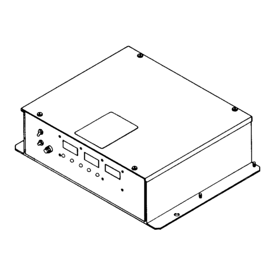
- Page 30 Figure A Control Box OM-883 Page 1...
- Page 31 Part Item Dia. Mkgs. Description Quantity Figure A Control Box CONTROL PANEL (Fig B Pg4) 116 774 RETAINER, screw No. 2 010 855 FASTENER, screw-hd No. 2 010 853 LABEL, warning electric shock can kill etc 070 634 COVER, top + 109 026 HEAT SINK 079 683...
- Page 32 117836 STAND-OFF, No. 6-32 x 5/8 x 1/4 hex 073 756 PLG2O,21 HOUSING, terminal header 14 pin 081 380 LABEL, Miller robot computer interface 112 254 089 032 LENS, led 4341 046 432 HOLDER, fuse FUSE, miniature glass 10 amp 250 volts *012 655 NUT, speed No.
- Page 33 Part Item Dia. Description Quantity Mkgs. Item 1) Figure B 116 774 Control Panel (Fig A Pg 2 071 642 CIRCUIT CARD, digital motor speed (Fig B2 Pg 8) 083 147 screw 8-10 push in GROMMET, RELAY, enclosed 24 volts dc DPDT 109 099 TRANSFORMER, control RECTIFIER, integrated 30 amp 400 volts...
- Page 34 RI 7 F7T7 ~LiLJ RI5CR2 — — ~IoII ‘a ‘a 0’ — 0’ DILJ [III] D2E] ~RI2 ~fj~ +Qc9 ASSEMBLY UQWUL~I)~ <<<<<<<<<< — ‘C RCI4 RCI5 RCI6 Ref. C-116 526 COMPONENTS TO BE REPLACED BY QUALIFIED PERSONNEL ONLY Figure Bi Circuit Card, Voltage OM-883 Page 5...
- Page 35 Dia. Part Description Quantity Mkgs. Figure Bi 116 528 Circuit Card, Voltage Control (Fig B Pg 4 Item 20) 096275 IC, Iinear324 159 IC,linear358 039 482 CAPACITOR, electrolyte 100 uf 35 volts dc Cl ,2 000 348 CAPACITOR, tantalum 0.47 uf 35 volts C3,4 C5-8,11 073 739 CAPACITOR, ceramicO.l uf50voltsdc...
- Page 36 449-0 COMPONENTS TO BE REPLACED BY Ref. D-093 QUALIFIED PERSONNEL ONLY Figure B2 Circuit Card, Motor Speed OM-883 Page 7...
- Page 37 Dia. Part Description Quantity Mkgs. Figure B2 071 642 Circuit Card, Digital Motor Speed (Fig B Pg 4 Item 1) 009 159 IC, linear 358 A50-53 CAPACITOR, electrolyte 100 uf 35 volts dc 039 482 CAPACITOR, mylar 0.0022 uf 200 volts dc C5 1 031 699 CAPACITOR, ceramic 0.1 uf50voltsdc...
- Page 38 Part Dia. Mkgs. Description Quantity Figure B3 113 221 Circuit Card, Interface (Fig B Pg 4 Item 21) 009 159 IC, linear 358 CAPACITOR, electrolyte 100 uf35voltsdc 039 482 000 348 CAPACITOR, tantalum 0.47 uf 35 volts CAPACITOR, tantalum 1 uf 35 volts dc 072 130 CAPACITOR, tantalum 2.2 uf 20 volts 005 023...
- Page 39 Dia. Part Description Quantity Mkgs. Figure B4 110 565 Circuit Card, Interface (Fig B Pg 4 Item 16) Cl -6,9-14,46,47 CAPACITOR, ceramic 0.005 uf 1000 volts dc C20-25,28-33 ,48,49 CAPACITOR, ceramic 0.1 uf500voltsdc LI -3,5-7,9 110 190 CHOKE, 1000 UH RC2 1 TERMINAL, header 14 pin 089 347...
- Page 40 Dia. Part Description Quantity Mkgs. Figure C 117 836 Circuit Card, Meter (Fig A Pg 3 Item 49) C1,2 CAPACITOR, tantalum 0.47 uf 35 volts 000 348 C3-5 073 739 CAPACITOR, ceramic 0.1 uf 50 volts dc DIODE, signal 0.020 amp 75 volts SP Dl.2 028 351 METER, DCO-200MV...
- Page 41 Item Dia. Part Mkgs. Description Quantity Figure D 117 617 Control Box, Gas/Current Sensor LABEL, warning general precautionary 047 497 WRAPPER +079 682 REED RELAY, current 079 687 CASE SECTION, bottom/front/sides 109 021 CABLE, No. 182/c (order byft) 049 455 CONNECTOR, clamp-cable 1/2 inch 115 104 BUSHING, snap 1-3/8 IDx 1-3/4 mtg hole...
Need help?
Do you have a question about the MR-5/PULSTAR 450 and is the answer not in the manual?
Questions and answers