Table of Contents
Advertisement
Quick Links
Advertisement
Table of Contents

Related Manuals for INNOVASON Eclipse


Summary of Contents for INNOVASON Eclipse
- Page 1 Eclipse User Guide Version: Edition: Sept 2010...
- Page 2 All entries in this document have been thoroughly checked; however no guarantee for correctness can be given. Innovason cannot be held responsible for any misleading or incorrect information provided throughout this manual.
-
Page 3: New In Nova 2
Nova Version 2.0 software introduces a number of new and improved features. If you are familiar with Eclipse, then use this list to locate more information on each topic. You can find instructions on how to install the new version of Nova software on Page 503. - Page 4 I/O patching can now be controlled for any Ethersound device detected on the network. In addition, the Nova software supports parameter control for specially supported Ethersound devices. These include Digigram’s Aqonda 16, Innovason’s SR-16 and Neumann’s DMI-8. See Page 273.
-
Page 5: Table Of Contents
Nova Software Internal Effects (FM-8VB Card) Console Reset and Automation The Standard Template CHAPTER 2: INSTALLATION Introduction Before Installing This Device The Standard Eclipse Package Handling and Transportation Dimensions and Weight Ambient Conditions Power System Connections Audio Connections Switching on the Power... -
Page 6: Table Of Contents
CHAPTER 5: CONSOLE OPERATION Introduction Fader Strips and the Smart Panel Fader Strips: User Pot Assignment Fader Strips: Pot Configurations Input Channels Smart Faders (SFADs) Mix Busses Mix Bus Sends Output Channels Stereo Channels VCAs Assignable Delays Labels Monitoring Talkback Eclipse User Guide... - Page 7 Sequence Playout The Play List (Automation) Automation Enable Buttons Processing Libraries Personal Mixes CHAPTER 8: UTILITIES & PREFERENCES Introduction FLAT (Parameter Reset) Copy and Paste Over Ram Relax (Automation Isolate) Request Mode Pre/Pan Link Cards Linking Offline Mode Eclipse User Guide...
- Page 8 Replacing the M.A.R.S. Hard Disk CHAPTER 11: TECHNICAL PROCEDURES Using M.A.R.S as a Backup for Nova Installing a New Release of Nova Software Resolving Communication Issues The System Setup Window APPENDICES Appendix A: The Standard Template Appendix B: Plug-in Effects Eclipse User Guide...
- Page 9 Table of Contents GLOSSARY TECHNICAL DATA Control Surface Audio Rack I/O and FX cards Options INDEX DIRECTORY Eclipse User Guide...
-
Page 10: About This Manual
About This Manual About This Manual How to Use This Manual Before we guide you through the operation of the Eclipse, first a few words about this manual. Chapter 1 introduces the console. Read this chapter to learn more about the system’s concepts and capabilities. -
Page 11: Conventions
Screenshots Please note that most of the Nova screenshots used in this manual have been taken offline. As a result, meters may be shown at full scale rather than at normal operating levels. 12/ 526 Eclipse User Guide... -
Page 12: Chapter 1: Overview Welcome
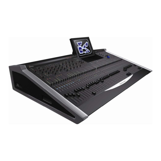
Chapter 1: Overview Welcome Chapter 1: Overview Welcome Eclipse is a powerful live mixing and recording console with the flexibility to adapt to Front of House (FOH), Monitors or OB van applications. Control Surface Overview Fader Strips The lower half of the Eclipse control surface features 48 Fader strips each with its own VU meter, rotary control (gain, pan or user), Label, ID, MUTE, CUE and fader select (SEL) button. - Page 13 Once a SEL button is active (flashing), these panels offer direct control of all settings – gain, insert switching, low cut filter, delay, dynamics, equalisation and panning. The controls work in conjunction with the Main Mix display which provides graphical feedback on the selected channel: 14/ 526 Eclipse User Guide...
- Page 14 User Defined Panel The USER DEFINED panel provides six VU meters, four rotary controls and four switches. Functions are assigned to each control from the “UTIL -> User defined assignment” menu. Eclipse User Guide 15/ 526...
- Page 15 Touch-Screen The console screen is a touch-screen display which can be switched between two control computers: • NOVA – Eclipse’s management software. Nova controls the console and stores/recalls mix settings. • M.A.R.S. (Multitrack Audio Recording System) – Eclipse’s integrated 64-track hard disk recorder.
- Page 16 Below the Power indicators are the console’s talkback, monitoring and headphone controls. Eclipse includes a stereo monitor bus which may be switched to three different monitor outputs. In addition, a headphone output is provided at the front of the console (1/4” jack).
-
Page 17: System Overview
Chapter 1: Overview System Overview System Overview Unlike an analogue console, Eclipse consists of much more than just the operating surface; a system may incorporate three physical components: • Console – houses the console’s DSP processing and master control, six slots for local i/o and internal effects cards, and an internal PC running the Nova software. - Page 18 The Standard Eclipse I/O Package So that you know what to expect, particularly when arriving to work on a rental console, Eclipse is delivered with a standard package of i/o and internal effects cards which consists of: • 1 DioCore – remote stage i/o with:...
- Page 19 Audio recording is managed by the M.A.R.S. control computer (separate from Nova), and audio files are stored on the removable hard disk at the rear of the Eclipse frame. A dedicated control panel switches the touch-screen between M.A.R.S. and Nova, and provides rapid access to recording and playback functions: Additional functions are accessible from the M.A.R.S.
- Page 20 In addition, the Nova software supports parameter control for specially supported Ethersound devices. These include Digigram’s Aqonda 16, Innovason’s SR-16 and Neumann’s DMI-8. For these devices, parameters such as analogue input gain can be controlled remotely from Eclipse: Eclipse User Guide 21/ 526...
- Page 21 System Overview Audio Networking Ethersound may also be used to link I/O between consoles. The example below shows two Innovason consoles sharing resources from two DioCores: If more than 64 inputs and 64 outputs are required on stage, then an additional unit (the Muxipaire StageBox) may be added.
-
Page 22: Signal Flow
• Pre-fader insert (external device or internal effects bay) • Pan (or Balance and Width on stereo channels) • Main level, Mute and Cue • Aux send level (pre-fader, post-fader or independent) • Matrix send level (pre or post-fader) Eclipse User Guide 23/ 526... - Page 23 1e’/e, graphic EQ, etc. The following diagram shows the division between processing on the I/O cards and processing on Eclipse’s DSP module: Note that in addition to the 48 configurable mix busses, a stereo bus is included for monitoring.
-
Page 24: Channel Types
Chapter 1: Overview Channel Types Channel Types Eclipse has 48 Fader Strips plus 48 Smart Panel controllers (available in 4 layers: A, B, C and D). Each may control any of the following channel types allowing you to lay out your source channels, bus masters and VCAs where you want them: •... -
Page 25: Smart Faders (Sfads)
Fader Strip or Smart Panel controller. However, in order to manage larger shows where the number of sources may exceed your physical faders, Eclipse provides a unique “layering” solution – Smart Faders (SFADs). This solution works by using a Smart VCA (SVCA) to control a number of input slave channels. -
Page 26: Nova Software
Chapter 1: Overview Nova Software Nova Software “Nova” is the name of Eclipse’s management software. It runs on the console’s control computer during live operation, and may also run offline on a PC. This allows you to build a configuration on the way to a venue and load it to the console when you arrive. - Page 27 Chapter 1: Overview Nova Software Digital Patching In addition to powerful mixing features, Eclipse includes a digital patch accessible from the Nova PATCH INPUT, PATCH OUTPUT and PATCH DIRECT displays: All three displays are similar in operation: • PATCH INPUT – patches physical sources to channels.
-
Page 28: Internal Effects (Fm-8Vb Card)
The effects processing is provided by the FM-8VB card. Two of these cards are fitted to the rear of the console as part of the standard Eclipse package. You may fit more cards (up to 6) providing you have spare slots. -
Page 29: Console Reset And Automation
Chapter 1: Overview Console Reset and Automation Console Reset and Automation One of the major benefits of the Eclipse is the ability to save and load all the settings required for a particular show or application. Files and Pages Console settings are stored and recalled from a “File” on the Nova control computer;... - Page 30 Nova control computer and may be exported to USB for transfer to other systems. For full details on Files, Pages, Automation and all other data storage functions, please see Chapter 7 (Page 341). Eclipse User Guide 31/ 526...
-
Page 31: The Standard Template
The Standard Template In this brief overview, we hope you have an idea of how flexible Eclipse can be. So to reduce your setup time and make the console easy to operate ‘out of the box’, each console is shipped with a pre-installed standard template File. Load this... -
Page 32: Chapter 2: Installation
Eclipse package including M.A.R.S. If your system contains non-standard components or you wish to learn more about networking multiple Innovason consoles, please refer to Page 263 and the “Eclipse Technical Manual”. Eclipse User Guide 33/ 526... -
Page 33: Before Installing This Device
Therefore do not open the devices other than to perform the procedures described in this manual. • Any swapping of modules MUST be performed with the device switched off and disconnected from the mains supply. 34/ 526 Eclipse User Guide... -
Page 34: The Standard Eclipse Package
Chapter 2: Installation The Standard Eclipse Package The Standard Eclipse Package A standard Eclipse consists of two physical components: • 1 DioCore providing stage I/O: o 7 SI-8D3 cards = 56 mic preamps o 1 UM-8PO card = 8 outputs (Line/AES/ADAT) •... - Page 35 The card provides a choice of BNC or optical Receive and Transmit connections to a remote StageBox. A Muxipaire Stagebox is an option on the Eclipse system, see Page 285 for more details. You will also find three connections for synchronisation: •...
- Page 36 There are then six I/O card slots which may be fitted with any combination of I/O or internal FX cards. See Page 19 for an overview of the available options. The standard Eclipse package is delivered with five I/O cards leaving one slot available for future expansion: Card...
- Page 37 DioCore networks. The standard CAT5 connections allow the DioCore to be located up to 100m from the Eclipse control surface. You can find details on DioCore networking on Page 263.
- Page 38 Chapter 2: Installation The Standard Eclipse Package I/O Cards The DioCore provides eight I/O card slots which may be fitted with any combination of I/O cards (the FX card is not managed by the DioCore). See Page 19 for an overview of the available options.
-
Page 39: Handling And Transportation
Warning Do not allow liquid or any foreign object to enter the Eclipse or allow the Eclipse to become wet. Fire or electrical shock may result. 40/ 526... -
Page 40: Dimensions And Weight
Dimensions and Weight Dimensions and Weight Control Surface The Eclipse control surface is supplied with a flight case and protective cover. The dimensions and weight of a console fitted with the standard I/O package are: Dimensions (H x W x D):... - Page 41 DioCore fitted with the standard I/O package are: Dimensions (H x W x D): Weight DioCore only 12.3 x 19 x 12,2” 44lb / 20Kg DioCore with 29 x 20.6 x 24.6” 59.5lb / 27Kg flight case 42/ 526 Eclipse User Guide...
-
Page 42: Ambient Conditions
Chapter 2: Installation Ambient Conditions Ambient Conditions Proper operation of the Eclipse system components can only be guaranteed at the following ambient temperatures: Component Ambient Operating Temperature Control Surface between 50°F and 95°F (10°C and 35°C) DioCore between 50°F and 90°F (10°C and 32°C) Warning •... -
Page 43: Power
The control surface and DioCore can be powered by a voltage between 90 and 253 volts AC, at 46-63Hz The maximum power consumption of the DioCore is 300W. Warning Only supply the input voltages described. 44/ 526 Eclipse User Guide... -
Page 44: System Connections
• Ethersound link between the console (OUT of the DioEs module) and M.A.R.S IN. These connections allow you to play back a demo song from M.A.R.S. without connecting the DioCore. Simply apply power to the console PSUs and follow the instructions on Page 448. Eclipse User Guide 45/ 526... - Page 45 The diagram below shows the Ethersound connections and audio streaming for a standard Eclipse package: Eclipse is the Primary Master of this network; M.A.R.S. is connected at the end of the chain. Mic preamps from the DioCore are patched downstream onto the Ethersound channels so that they can be recorded to M.A.R.S.
- Page 46 Remove the pre-installed Ethersound cable from Eclipse (the OUT on the DioES module) to the MARS (IN): Connect the Ethersound OUT from Eclipse (the OUT on the DIOEs module) to the IN of the DioCore. Connect the Ethersound OUT from the DioCore to the IN of M.A.R.S.
- Page 47 Chapter 2: Installation System Connections System Clock Eclipse offers a fully redundant clock source structure with external clocking options (Wordclock or AES) and an internal sync generator. This allows the console to be clocked from a choice of sync sources and recover from loss of external sync.
- Page 48 (e.g. it is the first in a network of several consoles or DioCores), you will need to synchronise the console to the Ethersound clock generated by the primary master. Connect this BNC to the WC IN of the MCoptical card to achieve the desired result. Eclipse User Guide 49/ 526...
- Page 49 (You can also restart each computer from the console keyboard, see Page 500.) Note that M.A.R.S. can be used as a backup for the Nova computer in the unlikely event of a failure. See Chapter 11 for details. 50/ 526 Eclipse User Guide...
- Page 50 Littlelite Connectors On the very top of the console you will find two 4-pin littlelite connectors. You can control the brightness of these lights from a rotary control on the USER DEFINED panel, see Page 322. Eclipse User Guide 51/ 526...
-
Page 51: Audio Connections
Chapter 2: Installation Audio Connections Audio Connections Eclipse’s I/O interfaces use the standard audio connectors commonly found in professional audio. Analogue-to-digital converters and digital audio connections operate at 24-bit, 48kHz, except the DI-8Src card which accepts sampling frequencies from 32kHz to 56kHz. - Page 52 This card provides 8 channels of internal effects. There are no audio i/o connections on these cards, as they provide internally routed effects. Each card includes a ¼” jack connector (TAP TEMPO) which is reserved for future implementation. Eclipse User Guide 53/ 526...
- Page 53 On the front of the console you will also find: • ¼” stereo jack – headphone output. • XLR – talkback input. These connections are used for the console’s Headphone monitoring, see Page 210, and engineer talkback, see Page 218. 54/ 526 Eclipse User Guide...
-
Page 54: Switching On The Power
The POWER status LEDs on the front panel of the console should turn green for correct operation: If an LED is red, then the power supply or voltage rail has failed. Please consult the “Eclipse Technical Manual” for further details. The console may take between 30-60 seconds to boot, depending on the last File loaded and I/O configuration. -
Page 55: Checking The Hardware Status
Page 270. Also, a third status colour (orange) indicates a data error; check your Ethersound connections and cable length. The MARS LED may also be red if MARS has not booted correctly. Reboot the M.A.R.S. control computer, see Page 496. 56/ 526 Eclipse User Guide... -
Page 56: Chapter 3: Operating Principles
Chapter 4 which provides a “Getting Started” guide to loading and working from the standard template File. To mix on Eclipse there are three principle control areas you will use: • The Fader and Smart Panel Strips •... -
Page 57: Fader Strips And The Smart Panel
Fader Strips and the Smart Panel Fader Strips and the Smart Panel Eclipse provides 48 Fader strips plus 48 Smart Panel rotary controllers (available in 4 layers: A, B, C and D). Each may control any input, output (Aux, Group, Master or Matrix) or act as a VCA or Smart Fader. -
Page 58: Fader Strips
The function of the rotary control is switched globally using the Pot. button beside the trackball: Press the Pot. button to cycle through the three options: Gain, Pan or User defined. A green LED indicates the selected mode. Eclipse User Guide 59/ 526... - Page 59 On VCA Fader strips, the rotary control has no function. On Smart VCA Fader strips, Gain adjusts the active slave channel; this is the slave with a fully lit Label, see Page 156. Pan controls the composite Pan, see Page 155. 60/ 526 Eclipse User Guide...
- Page 60 See Page 200 for more details on Labels. Note that on Aux channels, the name of the Personal Mix (e.g. John) takes priority over the channel Label if a Personal Mix is loaded. See Page 387 for details. Eclipse User Guide 61/ 526...
- Page 61 Each fader also has a notch which you will feel when you move the fader. This indicates the last level you set for the channel, and is a great way to tell if your mix is getting louder or quieter! 62/ 526 Eclipse User Guide...
-
Page 62: Smart Panel "Strips
Press and hold the layer button – e.g. A: The Smart Layer Name pop-up appears. Type in a name (up to 4 characters) from the console keyboard. Press OK or [ENTER] to confirm. The new Label appears beside the A button. Eclipse User Guide 63/ 526... - Page 63 Press down on the rotary control to turn Cue on or off. When active the CUE LED lights. Note that a Smart Panel “strip” has no separate rotary control for Gain/Pan/User. To control these functions, you must assign the Smart Panel controller to the Selected Channel. 64/ 526 Eclipse User Guide...
-
Page 64: The Nova Touch-Screen
TRANSPORT panel: • NOVA – the Nova mix management software. • M.A.R.S. – the M.A.R.S. hard disk recorder software (see Chapter 10). Press NOVA to switch control to the Nova displays: Eclipse User Guide 65/ 526... - Page 65 Main Mix. You can use UTILITIES buttons, the trackball or keyboard to open up different displays such as PATCH IN, PATCH OUT, etc. Note that the Main Mix, shown above, acts as the default display. Think of this as ‘home’. 66/ 526 Eclipse User Guide...
- Page 66 This strip of LEDs displays the status of the system. LEDs are green if Status the hardware component is operating correctly. See Page 56. Let’s look at the Selected Channel and DESK/SMART PANEL overview in more detail. Eclipse User Guide 67/ 526...
- Page 67 The SEL button and Label on the input should be flashing. Reach up to the PARAM EQ panel and adjust the EQ controls. Any changes you make are shown on the Main Mix display shown above. 68/ 526 Eclipse User Guide...
- Page 68 In our example, both the COMPRESSOR and EQUALIZER are turned on. Push-button parameters, such as 48V, and rotary controls, such as Gain, can be adjusted from the display as well as the console surface, see Page 87. Eclipse User Guide 69/ 526...
- Page 69 Note that if the input channel is stereo, then the text STEREO appears beside the Channel tab: You can deploy the left and right components of a stereo input to the Smart Panel using the on-screen EDIT button, see Page 189 for details. 70/ 526 Eclipse User Guide...
- Page 70 Note that if the output is stereo, then the text STEREO appears beside the Output tab: You can deploy the left, right and centre components of a stereo output to the Smart Panel using the on-screen EDIT button, see Page 189 for details. Eclipse User Guide 71/ 526...
- Page 71 Note also that on Aux channels, an arrow appears beside the patch name. This provides access to Personal Mixes which may be loaded to any Aux in order to recall personal monitor mixes for specific musicians, see Page 387. 72/ 526 Eclipse User Guide...
- Page 72 Auxes are stereo. Note that the display changes as you change the selected channel to provide forward or reverse interrogation of routing and send levels. Eclipse User Guide 73/ 526...
-
Page 73: Routing, Sends And The Sel Button
Routing, Sends and the SEL Button Routing, Sends and the SEL Button Eclipse uses a reciprocal routing system. Both bus routing and sends are set in one operation. This means that the faders (or Smart Panel controllers) can be operating in one of two modes: •... - Page 74 Aux sets the pan for the aux send. See Page 164 for details. You can also set a General Preferences option so that when an input is routed to an Aux, the Aux send is automatically set to 0dB, see Page 428. Eclipse User Guide 75/ 526...
- Page 75 Aux and then press the SEL buttons on the input faders: • SEL lit steady state = assigned. • SEL unlit = not assigned. You can route to multiple outputs in one operation using the multiple assign method described on Page 78. 76/ 526 Eclipse User Guide...
- Page 76 See Page 164 for more details. You can also set a General Preferences option so that when an input is routed to an Aux, the Aux send is automatically set to 0dB, see Page 428. Eclipse User Guide 77/ 526...
- Page 77 Note that you can only make multiple assignments in this way if all the channels you wish to select begin in the same state – either all on (SEL lit) or all off (SEL unlit). 78/ 526 Eclipse User Guide...
- Page 78 • You can move the console faders to quickly set Smart Panel levels (send or main level depending on the channel type). Remember to select the DESK tab to return to normal Fader strip and Main Mix display operation. Eclipse User Guide 79/ 526...
- Page 79 Aux faders control the aux sends. • In - input channel faders always control main level and not Aux send level. • Aux - Aux channel faders always control Aux master level and never Aux send levels. 80/ 526 Eclipse User Guide...
-
Page 80: Nova Operating Principles
Builder VCAs, etc.) to the 48 Faders and Smart Panel controllers. UTIL Over Ram Overwrite parameters into stored Pages within a File. e.g. to overwrite a new mic gain into all Pages for a show. Eclipse User Guide 81/ 526... - Page 81 M.A.R.S. Virtual Sound Check Switch to VSC mode to playback a virtual sound check from M.A.R.S. M.A.R.S. Broadway Very similar to VSC mode, but you can switch each channel to playback on an individual basis. 82/ 526 Eclipse User Guide...
- Page 82 Using the trackball, click on the X at the top right of the display: Note that if you click on the X at the top right of the Main Mix display, you will shut down the Nova software. Eclipse User Guide 83/ 526...
- Page 83 File. To close a floating window, such as the Geq Editor, click on the red and white X at the top right of the window. 84/ 526 Eclipse User Guide...
- Page 84 Press the OK or CANCEL buttons beside the trackball to confirm or cancel the operation: Or, click on the screen buttons. If you are using the console keyboard, you can also press [ENTER] to confirm or [Esc] to cancel. Eclipse User Guide 85/ 526...
- Page 85 [F1], or selecting the “UTIL -> Help” menu. Often you will use the keyboard to select a function by pressing the letter underlined on-screen; in the PAN display, shown opposite, pressing [O] selects On, [P] selects Prefader, and [I] selects Independent. 86/ 526 Eclipse User Guide...
- Page 86 Delay to a channel. In most instances, the screen text will guide you: For more details on using a mouse and keyboard to prepare an offline configuration, please refer to Chapter 9. Eclipse User Guide 87/ 526...
-
Page 87: Chapter 4: Getting Started (The Standard Template)
(The Standard Template) Introduction Having covered the operating principles of the Eclipse, let’s look at how to get started on the console. To do this we are going to load and work with the standard template File (Templ1) which is pre-installed on every console. -
Page 88: Loading A File
To load the file: Using the trackball select “FILE -> Load” from the main menus. The FILE LOAD window appears on the Nova screen: Select the File you wish to load – Templ1. Confirm by pressing OK. Eclipse User Guide 89/ 526... - Page 89 (INNOVA). When the load is complete, the console resets to the settings stored in this Page. Note that the active File and current Page names are shown at the top of the Main Mix display: 90/ 526 Eclipse User Guide...
- Page 90 Nova now saves all Pages within the desk memory into a new File on its hard disk called Show1. You will see the progress of the save. When the Save is complete, the new File name appears at the top of the Main Mix display: Eclipse User Guide 91/ 526...
-
Page 91: Interrogating The Fader Strips
– for example, switch EQ on across all Auxes – then use the Fast Configuration window described on Page 318. Please see Appendix A (Page 508) for full details on how to connect your audio devices. 92/ 526 Eclipse User Guide... -
Page 92: Interrogating The Smart Panel
8 mic/line inputs at the rear of the console (SI-8D3 card). Layer C (VCAs) This layer provides 12 VCA channels. Layer D (MATX) This layer provides 12 Matrix outputs patched to local UM-8 outputs at the rear of the console. Eclipse User Guide 93/ 526... -
Page 93: Signal In To Out
Chapter 4: Getting Started (The Standard Template) Signal In to Out Signal In to Out Normally on Eclipse, there are three operations required to get signal through the console: • PATCH IN – patch your audio sources to input channels •... -
Page 94: Default Patching
Smart Panel controls on Layer B are patched from the 8 mic/line inputs at the rear of the console: You can view or modify this patching from the PATCH IN grid as described on Page 231. Eclipse User Guide 95/ 526... - Page 95 The four stereo Auxes (Fader strips 41 to 44) are patched to the 8 UM-8PO outputs in the DioCore. Therefore they also feature Output processing. You can view or modify this patching from the PATCH OUT grid, as described on Page 247: 96/ 526 Eclipse User Guide...
- Page 96 Smart Panel Layer A FX send and return channels. You can view or modify the FX Send patching from the PATCH OUT grid and FX Return patching from the PATCH IN: Eclipse User Guide 97/ 526...
- Page 97 And the first 8 Line Level ins and outs (on the DSP card at the rear of the console) are configured for eight mono external insert points. You can view or modify this patching from the PATCH DIRECT grid, as described on Page 256: 98/ 526 Eclipse User Guide...
-
Page 98: Default Bus Routing
If you want to know more about Mix Busses, see Page 159. For details on Aux (and Matrix) sends, see Page 163. For the moment we will assume that you are working with the basic routing loaded by the Templ1. Eclipse User Guide 99/ 526... -
Page 99: Your First Mix
Press SEL on the input channel. This assigns the channel to the INPUT, DYNAMIC, DELAY and PARAM EQ panels. Then press the 48V button on the INPUT panel. You can also adjust analogue gain, digital trim or phase. 100/ 526 Eclipse User Guide... - Page 100 Dependent panning affects all stereo bus sends – in our template, this is the stereo Master and stereo Aux sends. Note that panning to Auxes may be independent for each Aux output. See Page 126 for details. Eclipse User Guide 101/ 526...
- Page 101 You can now use any of the front panel controls to adjust EQ, Compressor, Gate, etc.: Controls are laid out to match the controls on the Main Mix display: For a full explanation of EQ, Dynamics and other processing sections, please see Page 131. 102/ 526 Eclipse User Guide...
- Page 102 Unactivate it when the Graphiq EQ is set. While Geq editor is activated, the 31-bands of Graphic EQ are temporarily assigned down onto the first 31 faders; Fader 32 allows you to change the scale of the Graphic: Eclipse User Guide 103/ 526...
- Page 103 At any time you can adjust the other processing sections from the front panel controls: To view the parameters on the Main Mix display, close the Geq window: For more information on output processing, see Page 173. 104/ 526 Eclipse User Guide...
- Page 104 Move the input faders – in our example, Faders 1 to 8. The faders adjust the send levels to the selected Aux. You can confirm this by looking at the upper row of faders on the Main Mix display: Eclipse User Guide 105/ 526...
- Page 105 Repeat steps 3 to 6 to setup the next Aux send mix. You can change the Aux assignments at any time by pressing and holding the flashing AUX SEL button while you press the SEL buttons on your input faders. 106/ 526 Eclipse User Guide...
- Page 106 Note that processing is applied to the UM8 output card (as for your stereo Master). You can adjust the left and right sides of the Aux output by deploying the component channels to the Smart Panel, see Page 189 for details. Eclipse User Guide 107/ 526...
- Page 107 The Main Mix display also updates and shows that the output from this Aux send is patched to a stereo effects bay: You can see that the bay has been configured with a Just-Verb plug-in. 108/ 526 Eclipse User Guide...
- Page 108 You can confirm that you are adjusting the Aux send level by flipping the Main Mix display to the SMART PANEL and looking at the upper row of faders as you move the FX1 control: You should also see level on the FX1 VU meter. Eclipse User Guide 109/ 526...
- Page 109 EQ, DYNAMICS, etc. panels. Note that you can adjust the left and right sides independently by deploying the component channels to the Smart Panel, see Page 189 for details. 110/ 526 Eclipse User Guide...
- Page 110 Double-click on the Just-Verb module to open the Effects Editor window: If you want the Effects Editor window to open every time you select the FX send or return channels, then turn on Display Hold as shown above. Eclipse User Guide 111/ 526...
- Page 111 Press the Smart Panel A, B, C and D buttons to page through the different sets of effects controls. When are finished, deselect FX Edit and press SEL on one of your input faders to return your input channels to their normal operation (main channel level). 112/ 526 Eclipse User Guide...
- Page 112 As this is an external insert, you need to control settings on the outboard device! However, if you insert an internal effects bay, you can control and store its settings by clicking on the InsPre processing tab. See Page 309 for more details on Inserts. Eclipse User Guide 113/ 526...
- Page 113 Note that a VCA controls level and MUTE only; you cannot apply master control of EQ, Dynamics, etc and you cannot CUE a VCA. Note that you may route a channel to multiple VCAs if you wish. For more details, see Page 193. 114/ 526 Eclipse User Guide...
- Page 114 [ALT] + [F3]; each time you press OK, the next strip is selected. Or, having opened the Label window, use the up and down arrows to navigate among the channels of the desk. For more details on Labels, see Page 200. Eclipse User Guide 115/ 526...
- Page 115 Chapter 4: Getting Started (The Standard Template) Your First Mix Monitoring and Headphones Eclipse provides a dedicated stereo bus for monitoring. This bus can feed up to three monitor and headphone circuits, each with independent level control. The Templ1 File patches the Monitor 01 circuit to UM-8PO outputs 15 and 16 on the rear of the console.
- Page 116 Only input channel CUEs can operate in Solo-in-Place. To make input channel CUE buttons exclusive, select Auto Cancel. To clear all CUE selections, press Clear Cue. For more details on Monitoring and Cue modes, please see Page 206. Eclipse User Guide 117/ 526...
-
Page 117: Saving Your Settings
Press the Save File button on the FILES/AUTO panel: (FILES/AUT0) “FILE -> Save” The button lights (red) as data is writing to the hard disk. See Chapter 7 for more details on Files and Pages. 118/ 526 Eclipse User Guide... -
Page 118: Chapter 5: Console Operation
• Monitoring – Page 206. • Talkback – Page 218. Note that channel Inserts, Internal Effects and the User Defined Panel are covered in Chapter 6. This is also where you can learn more about console configuration and patching. Eclipse User Guide 119/ 526... -
Page 119: Fader Strips And The Smart Panel
Fader Strips and the Smart Panel Fader Strips and the Smart Panel Channels are only active on Eclipse when they are assigned to the surface. In other words, what you see is what you get! Eclipse provides 48 Fader strips plus 48 Smart Panel rotary controllers (available in 4 layers: A, B, C and D). - Page 120 On the Fader strip, press and hold down the pot you wish to assign. The available functions flash in the Label displays on the Eclipse front panel: Keep holding down the pot, and press down on one of the flashing controls – e.g. EQ Band 1 GAIN.
- Page 121 Having assigned User pots across the console, you can copy these assignments into other Pages of the File using the OVERRAM display. Select the Faders pots option when choosing the Over Ram parameters, see Page 399 for details. 122/ 526 Eclipse User Guide...
-
Page 122: Fader Strips: Pot Configurations
Alternatively they can be opened from the VIEW menu: • VIEW -> Gain Configuration • VIEW -> Pan Configuration • VIEW -> User Configuration Select the option(s) required. Then press OK to make the configuration active. Eclipse User Guide 123/ 526... - Page 123 • Follow Input Section – the pot follows the choice of Analog or Trim made on the INPUT panel. • Opposite of Input Section - the pot follows the opposite choice of Analog or Trim made on the INPUT panel. 124/ 526 Eclipse User Guide...
- Page 124 • TIME HOLDING – enter a time (e.g. 2 seconds). This is the length of time for which the INFO pop-up window appears on the Nova display when you adjust a pot in Gain mode: Eclipse User Guide 125/ 526...
- Page 125 • TIME HOLDING – enter a time (e.g. 2 seconds). This is the length of time for which the INFO pop-up window appears on the Nova display when you adjust a pot in Pan mode (as for the Gain Pot configuration). 126/ 526 Eclipse User Guide...
- Page 126 The steady state SEL buttons indicate bus assignments to the selected Aux - in our example, a range of input channels are assigned to the Aux: If you move your input faders, you should be adjusting the Aux send levels. Eclipse User Guide 127/ 526...
- Page 127 Repeat for any other channels which require independent panning to the selected Aux. Then press SEL on your next stereo Aux channel and repeat the process to configure another send mix. 128/ 526 Eclipse User Guide...
- Page 128 You will need to use this display if you wish to switch Aux sends from dependent to independent pan when working offline. See Page 164 for details on this display. Eclipse User Guide 129/ 526...
- Page 129 • TIME HOLDING – enter a time (e.g. 2 seconds). This is the length of time for which the INFO pop-up window appears on the Nova display when you adjust a pot in Pan mode (as for the Gain Pot configuration). 130/ 526 Eclipse User Guide...
-
Page 130: Input Channels
(from the PATCH IN grid). Note that a stereo channel uses 2 mono DSP resources. For now, we are going to concentrate on a mono input channel. You can find more details on Stereo channels on Page 184. Eclipse User Guide 131/ 526... - Page 131 • DIO1 - this is the 4-character user Label for the source (also displayed above the input fader). For more details on Labels see Page 200. For more details on the Main Mix display see Page 67. 132/ 526 Eclipse User Guide...
- Page 132 The phantom power supply voltage is 48V, and its current is limited to 6mA. You can also enter settings from here – for example, click on the GAIN control to adjust input gain in 1.5dB steps. Eclipse User Guide 133/ 526...
- Page 133 Analogue Gain and digital Trim levels may also be adjusted from the console’s Fader strips, see Page 58 for details. If you want to adjust a source not assigned to a fader (e.g. a Talkback mic), use the PATCH DIRECT grid, see Page 256. 134/ 526 Eclipse User Guide...
- Page 134 VU meters are identical to those on the console surface but do not show Gate activity: • Main Mix display PEAK and VU Metering – these two meters always meter the selected input pre processing with VU (average) and PEAK characteristics: Eclipse User Guide 135/ 526...
- Page 135 Note that you can only use the ADJ mode if the console’s VU meters are pre-processing with a maximum hold time of 200ms. Therefore, when you activate this function, you will be presented with the following dialogue box: 136/ 526 Eclipse User Guide...
- Page 136 General Preferences, see Page 428. DELAY Eclipse offers a pool of 48 delays, assignable to any input or output (mix bus) channel. The delay time may be set up to 222ms and can be adjusted in samples, ms or metres. See Page 197 for details.
- Page 137 OUT metering as the front panel. Note that the red and yellow markers on the input level meter represent the gate and compressor thresholds: This area also includes a dynamics curve which shows the sum of both sections of processing: Gating plus Compression. 138/ 526 Eclipse User Guide...
- Page 138 Main Mix display. Also, keep an eye on the amount of gain reduction being applied using the gain Red. meter. You can reset the Compressor settings to flat using the FLAT button as described on Page 393. Eclipse User Guide 139/ 526...
- Page 139 The top LED illuminates in blue when the gate is fully closed; the two LEDs below illuminate in red to indicate -6dB or -12 dB of gain reduction. You can reset the Gate settings to flat using the FLAT button as described on Page 393. 140/ 526 Eclipse User Guide...
- Page 140 The front panel control layout is copied on the Main Mix display, and the display includes an EQ curve. Note that the EQ curve provides an overview of the combined parametric EQ and low cut filter sections: Eclipse User Guide 141/ 526...
- Page 141 • Gain: ±15 dB (in steps of 1 dB) plus a Notch (at -50 dB) • Q Factor: from 1/8 to 8 octaves (by the power of 2) Reduce the Gain to minimum to activate the Notch filter: 142/ 526 Eclipse User Guide...
- Page 142 Press down again on the Q Factor control to return the band to parametric EQ. You can reset the Parametric EQ settings to flat using the FLAT button as described on Page 393. Eclipse User Guide 143/ 526...
- Page 143 Turn the control to adjust the Left/Right position. The Pan position is indicated on the front panel and on the Main Mix display: Panning may also be adjusted from the console’s Fader strip pot, see Page 58. 144/ 526 Eclipse User Guide...
- Page 144 The main level for the selected input channel is shown on the Main Mix display as follows: You can also get an overview of all main levels across the DESK or SMART PANEL from the lower row of faders: Eclipse User Guide 145/ 526...
- Page 145 For input channels, the CUE button may be set to operate as PFL, AFL or SIP (Solo-in-Place). In addition, CUE can be additive or intercancel, and you can clear all CUEs. These options are set from the TB/MONITORING panel, see Page 206. 146/ 526 Eclipse User Guide...
- Page 146 The upper row of faders on the DESK or SMART PANEL Main Mix display provides confirmation of the send levels to your selected Aux: Note that this default fader mode (Dual) can be altered from the General Preferences window, see Page 428 for details. Eclipse User Guide 147/ 526...
- Page 147 SEL button on the selected input, or on the selected matrix in order to adjust matrix send levels from the faders. See Page 170 for full details. Routing to Aux, Matrix, Group and Master busses is covered in detail on Page 159. 148/ 526 Eclipse User Guide...
-
Page 148: Smart Faders (Sfads)
Fader strip or Smart Panel controller. However, to manage larger shows where the number of sources may exceed your physical faders, Eclipse provides a unique “layering” solution – Smart Faders (SFADs). This solution works by using a Smart VCA (SVCA) to control a number of input slave channels. - Page 149 Note that each input benefits for each console of its own channel processing. No need to be lost in the pre/post processing sending offered by the traditional other consoles. 150/ 526 Eclipse User Guide...
- Page 150 Note that for ease of operation, the Smart Fader zone must use contiguous Fader, or Smart Panel, strips and only one zone is allowed. The Smart Fader slaves (SZONE) are shown with a light blue ID – in our example, Faders 25 to 28: Eclipse User Guide 151/ 526...
- Page 151 Labels on the Fader strips and the faders close: Now press SEL on a Smart VCA channel – e.g. drum. This SVCA has four slaves which are deployed into the Smart Fader Zone: 152/ 526 Eclipse User Guide...
- Page 152 Press the SEL button to assign the input channel to the Selected Channel and adjust EQ, Dynamics, etc: If the slave channel is stereo, then it will behave as a normal stereo input channel. See Page 184 for details. Eclipse User Guide 153/ 526...
- Page 153 Note that you can deselect individual CUE buttons from the SZONE slaves if you wish. If you do this, then you will need to deselect all slave CUEs before you can re-activate them from the SVCA master. 154/ 526 Eclipse User Guide...
- Page 154 You can see the affect of any pan offsets on the Main Mix display. The following diagram shows the PAN position for two Smart Fader slaves (SFADs), and the resultant PAN display if you select the SVCA master: Eclipse User Guide 155/ 526...
- Page 155 It is now the BD K input channel which is active and will be controlled from the Selected Channel panels. Keep pressing the SEL button on the SVCA channel and you will see that it cycles through all the input slaves. 156/ 526 Eclipse User Guide...
- Page 156 (controlled by a Guitars Smart VCA), to the EQ on the Bass DI (controlled by a Bass Smart VCA) simply by pressing SEL on the Guitars or Bass SVCA channels. The diagram below summarises the control from the Smart Fader VCA channel (SVCA): Eclipse User Guide 157/ 526...
- Page 157 MUTE buttons. Pan each slave and adjust its initial EQ, Dynamics, etc. Now repeat these steps for each SVCA on the console. This will provide a good starting point for your mix. 158/ 526 Eclipse User Guide...
-
Page 158: Mix Busses
Note that up to 32 mix busses may be patched to the Muxipaire interfaces (at the rear of the console or in a Muxipaire Stagebox). There is no limit on mix bus patching to a DioCore (Ethersound interface). Please see the “Eclipse Technical Manual” for further details. Signal Flow Each of the 48 mix busses may be configured as an Aux, Group, Master or Matrix output. - Page 159 Please refer to Page 74 for an example of forward and reverse bus assign. Note that you can set a General Preferences option so that when an input is routed to an Aux, the Aux send is automatically set to 0dB, see Page 428. 160/ 526 Eclipse User Guide...
- Page 160 (from Auxes and Groups only) or summed, as shown below: Note that panning can only be applied on Aux or Group output channels. You cannot pan a Matrix or Master. Eclipse User Guide 161/ 526...
- Page 161 Note that the Matrix Sends may operate in Static assign or Active assign as described on Page 170. Note that this table applies to the Dual fader mode. This mode can be altered from the from the General Preferences window, see Page 428. 162/ 526 Eclipse User Guide...
-
Page 162: Mix Bus Sends
(other mix busses). Assignments to a stereo Matrix always follow the main channel Pan. The operation of Matrix Sends is a little different to Aux Sends. For details see Page 170. Eclipse User Guide 163/ 526... - Page 163 Groups from Auxes from Masters. Also notice that the bus assignment options vary depending on the type of bus – for example, the Master can only be assigned ON/off (PREFADER and INDEPENDENT are not available). 164/ 526 Eclipse User Guide...
- Page 164 Return to the DESK faders, and press SEL on a different input channel. The display updates to show assignments from the input. Now exit the PAN display by deselecting the Pre/Pan button or pressing CANCEL or [ESC]. Eclipse User Guide 165/ 526...
- Page 165 Smart Fader VCA, you can see the bus assignments and pan positions from each individual slave channel. Press SEL on a different output channel. The display updates to show assignments to the selected mix bus. 166/ 526 Eclipse User Guide...
- Page 166 Aux (e.g. AUX 1) from all 104 input channels: “GRID -> Pan” [F11] Now using the console keyboard choose your assignment mode: • Press [O] to select ON. • Press [P] to select PREFADER. • Press [I] to select INDEPENDENT. Eclipse User Guide 167/ 526...
- Page 167 4. When you have finished deselect the Pre/Pan button or press CANCEL or [ESC] to exit the PAN display. The console’s SEL buttons now return to showing and changing the status of On/Off bus assignments. 168/ 526 Eclipse User Guide...
- Page 168 The INFO window updates accordingly. You can set separate pan positions to multiple bus sends as long as each one is configured to be Independent of the main channel pan. Eclipse User Guide 169/ 526...
- Page 169 Matrix sends are always post-fader from output channels (other mix busses), but can be switched pre-fader or post-fader for all input channels. This option is set globally and is selected from the General Preferences window: PREF (USER DEFINED PANEL) “UTIL -> General Preferences” 170/ 526 Eclipse User Guide...
- Page 170 Matrix SEL button is pressed, your Master (and input, Aux, Group) faders are NOT adjusting their Master levels, but are adjusting the Matrix send level. For this reason, we recommend Static mode off which works as follows: Eclipse User Guide 171/ 526...
- Page 171 Now the faders on the console update to show the send levels to the selected Matrix. Keep holding the Matrix SEL button and move the faders to change the send levels. You can confirm the operation from the Main Mix display: 172/ 526 Eclipse User Guide...
-
Page 172: Output Channels
• Delay – assignable from a pool of 48 delay resources. • Pre-fader insert (external device, floating DSP resource or internal effects bay) • Pan • Main level, Mute and Cue • Post-fader insert (external device, floating DSP resource or internal effects bay) Eclipse User Guide 173/ 526... - Page 173 EQ, etc. The following diagram shows the division between processing on the I/O cards and processing on Eclipse’s DSP module: 174/ 526 Eclipse User Guide...
- Page 174 Chapter 5: Console Operation Output Channels: Internal “Floating” DSP Paths Internal “Floating” DSP Paths Eclipse provides 16 internal DSP paths which can be assigned to any output channel (mix bus). You should use the internal DSP when you want to process the mix bus rather than individual outputs.
- Page 175 You can now use the INPUT Trim, Ø DYNAMICS, DELAY, LOW CUT and PARAM EQ controls to adjust the internal processing parameters. The method of control is identical to that used on input channels, so please see Page 131 onwards for details. 176/ 526 Eclipse User Guide...
- Page 176 EQ, etc. Every UM8-PO output provides: • Output gain (adjustable from +10.5dB to +22 dB) • Phase reverse • Delay – up to 1365ms • Compressor/Limiter • Gate/Expander • 8-band Parametric EQ • 31-band Graphic EQ Eclipse User Guide 177/ 526...
- Page 177 If your output channel is a stereo LR or LRC bus, then use the STEREO EDIT button to access the Left, Right or Centre component channels, see Page 189 for details. 178/ 526 Eclipse User Guide...
- Page 178 PARAMETRIC EQ panel pages the EQ controls between parametric EQ bands 1 to 4 and 5 to 8, and the Graphic EQ. An overview of all EQ parameters is provided on the Main Mix display: Eclipse User Guide 179/ 526...
- Page 179 • Scale +/-6 or +/-18 – selects the fader range. You choose between -6 to +6dB or -18 to +18dB. • Display Hold – select this option and the Geq window will automatically appear each time the bus is selected. 180/ 526 Eclipse User Guide...
- Page 180 Fader 32 on the console switches the fader range, and is equivalent to the on-screen +/-6 to +/-18 button. Open or close the fader to activate the scale change. Eclipse User Guide 181/ 526...
- Page 181 The Geq window for the selected aux opens, and the frequencies are automatically assigned onto the console faders. When you have finished making changes, turn off the Geq button to return the faders to their normal operation and close the Geq window. 182/ 526 Eclipse User Guide...
- Page 182 Set the option to the desired status – for example, select the ON button. Then click and hold on the option. Keep holding and a confirmation box appears. Press OK and the setting will be applied across all Pages in memory. Eclipse User Guide 183/ 526...
-
Page 183: Stereo Channels
Stereo input and output channels are handled in a similar manner. This section describes the operation of a stereo input channel with additional notes for outputs where applicable. For details on configuring stereo inputs and mix busses, please see Pages 238 and 225. 184/ 526 Eclipse User Guide... - Page 184 Matrix faders 43 and 44, and the Master Fader (48) are stereo. Also, on the console surface, if the channel has not been renamed, then the default Labels are: • SIN (stereo input). • SAUX, SGRP, SMTX or SMST (stereo Aux, Group, Matrix or Master). Eclipse User Guide 185/ 526...
- Page 185 • Output channel processing – remember that for output channels to have signal processing, they must be routed to UM8 outputs or be assigned internal DSP resource. LR channels use two DSP resources; LRC channels use three DSP resources. 186/ 526 Eclipse User Guide...
- Page 186 The Main Mix display shows the position of the left (white) and right (red) inputs. BALANCE is highlighted in green when the control is set to its default value: Eclipse User Guide 187/ 526...
- Page 187 Turn clockwise to increase, or anticlockwise to decrease the width. Note that if you keep turning anticlockwise you can reverse left (white) and right (red). Having reduced the width, you can offset the channel by re-adjusting the balance control: 188/ 526 Eclipse User Guide...
- Page 188 The Main Mix display shows the left side of the channel: If this is an output channel, then it may be routed to more than one destination. Press SEL again to select the required destination: Eclipse User Guide 189/ 526...
- Page 189 You can now use the Smart Panel controls to adjust parameters for left, right or centre: • Turn one of the rotary controls to adjust the fader level. • Press SEL to assign to the selected channel; then adjust parameters in the usual manner. 190/ 526 Eclipse User Guide...
- Page 190 So, for example, if you have muted the left input in stereo EDIT mode, and then press MUTE on the master input fader, the status updates on both left and right sides. Eclipse User Guide 191/ 526...
- Page 191 However, you can still switch between the Left and Right component channels by clicking on the red button on the SEPARATE STEREO pop-up, and adjusting parameters from the Main Mix display in the usual manner: 192/ 526 Eclipse User Guide...
-
Page 192: Vcas
Chapter 5: Console Operation VCAs VCAs On Eclipse VCAs can be used to provide master control of main level and Mute for several input and/or output channels. You can configure as many VCAs as you like, using Fader strips or Smart Panel controllers. And, any combination of input,... - Page 193 When you unmute the VCA, the channel MUTE cancels. • MUTE steady state - the channel MUTE is active; it will not be affected by the VCA MUTE. To unmute the channel you must unmute both the VCA and the slave. 194/ 526 Eclipse User Guide...
- Page 194 The Channel LABEL window appears: You can enter a new 4-character Label from the keyboard. Confirm by pressing OK. The new Label appears on the Fader strip, or Smart Panel controller, and on the Main Mix display. Eclipse User Guide 195/ 526...
- Page 195 The diagram below shows the effect of each mode when a guitar channel (Guit) is assigned to three VCAs: The choice of VCA mode is made from the General Preferences window, see Page 428. 196/ 526 Eclipse User Guide...
-
Page 196: Assignable Delays
Chapter 5: Console Operation Assignable Delays Assignable Delays Eclipse offers a pool of 48 delays, assignable to any input or output (mix bus) channel. Each delay may be adjusted from 0 to 222ms. Note that assigning a delay to a stereo LR channel uses two delay resources;... - Page 197 You can assign a delay pre-fader AND post-fader if you wish to increase the overall delay time available for the output channel. Remember that UM8 outputs include delay within the output card processing (up to 1365ms). 198/ 526 Eclipse User Guide...
- Page 198 Note that when using an assignable delay on an output channel (mix bus), the minimum delay time is 12 samples. For technical reasons, it is not possible to set a value below this value. Eclipse User Guide 199/ 526...
-
Page 199: Labels
• DIOCH 14 – indicates that the input is connected via Ethersound channel 14. • ANALOG INPUT – indicates that the input is analogue. If the selected channel is not yet patched, then the Main Mix display shows NO PATCH: 200/ 526 Eclipse User Guide... - Page 200 STEREO EDIT mode, see Page 189 Note that on Aux channels, the name of the Personal Mix (e.g. John) takes priority over the channel Label if a Personal Mix is loaded. See Page 387 for details. Eclipse User Guide 201/ 526...
- Page 201 Confirm by pressing OK. The FADER Label appears on the Fader strip. The LEFT and RIGHT input Labels are used on the Main Mix and Patch displays. All other fields are for information only. 202/ 526 Eclipse User Guide...
- Page 202 Confirm by pressing OK. The FADER Label appears on the Fader strip. The LEFT and RIGHT output Labels are used on the Main Mix and Patch displays. All other fields are for information only. Eclipse User Guide 203/ 526...
- Page 203 Select the Fader or Smart Panel strip and press [F3] on the console keyboard. Enter a 4-character Label into the FADER field. Confirm by pressing OK. The new Label appears on the Fader strip, or Smart Panel controller, and on the Main Mix display. 204/ 526 Eclipse User Guide...
- Page 204 Enter the next 4-character Label and confirm with OK. If you wish to keep any existing Labels, then press OK to retain them. Continue labelling until you wish to exit. Press CANCEL to close the LABEL window. Eclipse User Guide 205/ 526...
-
Page 205: Monitoring
Chapter 5: Console Operation Monitoring Monitoring In addition to the 48 configurable mix busses, Eclipse provides a stereo CUE bus for monitoring. This bus can feed up to three monitor circuits and headphones, each with independent level and selector control: Only one Monitor circuit, plus Headphones, is active at a time. - Page 206 Monitor 2 output. Press Mono to mono the monitor bus. This button will stay active while you switch to different monitor outputs. Note that the Assign button on the TB/MONITORING panel is reserved for future implementation. Eclipse User Guide 207/ 526...
- Page 207 Notice how the orange monitor faders now represent the second circuit. Also note that the first monitor output has been muted; indicated by the red dots in the Mute column. Finally, press Monitor 03, and patch the third circuit: 208/ 526 Eclipse User Guide...
- Page 208 Note that once a monitor fader is assigned to the surface, the Level control on the TB/MONITORING panel has no function. Press the SEL button on the Monitoring fader to toggle between the left and right outputs of the monitor circuit. Eclipse User Guide 209/ 526...
- Page 209 APL for output channels. When APL is selected, the Headphones receive AFL. • Tick Select and the Headphone circuit monitors whichever channel is currently selected (SEL active). The Select bus is mono and monitors the selected channel pre-fader. 210/ 526 Eclipse User Guide...
- Page 210 As you move the control you will see the HEADPHONE circuit level appear at the top right of the Main Mix display: Note that the Headphone mute button and Push Delay function on the TB/MONITORING panel are reserved for future implementation. Eclipse User Guide 211/ 526...
- Page 211 CUEs. Note that the Master if no cue option, set from the Monitoring preferences window, prevents you from clearing the CUE buttons on Master channels. See Page 217 for details on Monitoring preferences. 212/ 526 Eclipse User Guide...
- Page 212 Note that to use this feature, the monitor circuit(s) MUST be patched to UM-8PO outputs. This is because the system uses a clever method of “copying” the DSP parameters onto the monitor output DSP. You can see this in the diagram below: Eclipse User Guide 213/ 526...
- Page 213 You can deselect individual CUE buttons from slave channels if you wish. If you do this, then you will need to deselect all slave CUEs before you can re-activate them from the Smart VCA master. 214/ 526 Eclipse User Guide...
- Page 214 300ms. The CUE button flashes to indicate it is now set for “Solo Safe”. Now press CUE a different input channel. Any channels in Solo Safe mode are not muted by the Solo-in- Place selection. Eclipse User Guide 215/ 526...
- Page 215 Press a CUE button on faders 13 to 16 and monitor circuit 01 is automatically selected. Press a CUE button on faders 19 to 24 and monitor circuit 02 is automatically selected. You can configure this operation for up to three monitor circuits. 216/ 526 Eclipse User Guide...
- Page 216 • Follow in select – when ticked, the monitor bus receives whichever input channel is currently selected (SEL active). SOLO IN PLACE • On – identical to turning on the SIP button on the TB/MONITORING panel. Eclipse User Guide 217/ 526...
-
Page 217: Talkback
Press SEL on the mix busses you wish to talk to. In our example, we have selected two Auxes: You can select as many Aux, Group, Master and Matrix busses as you wish. You cannot inject talkback to an input or VCA! 218/ 526 Eclipse User Guide... - Page 218 Uncheck this box if you wish to have a blank Talkback routing configuration each time you press a talkback control. As soon as you release the TB 1 control, talkback is cancelled and the Level control returns to monitor level. Eclipse User Guide 219/ 526...
-
Page 219: Chapter 6: Console Configuration
RELAX, etc.) are grid-type displays. They all behave in a similar manner, therefore once you understand one you will feel comfortable operating the others. For an example of how to work with any grid display, see the PATCH IN on Page 231. 220/ 526 Eclipse User Guide... -
Page 220: The Personal Console Builder
[ALT] + [C] Click on the DESK and SmartPanel tabs to switch view: The Smart Panel controllers are represented as 48 “faders”; the A, B, C and D markers represent the four layers of controls. Eclipse User Guide 221/ 526... - Page 221 • DEFAULT – loads a default configuration. This is factory configured and cannot be modified by the user. • UNDO – will undo any changes made in this visit. • OK – loads the displayed configuration to the console. 222/ 526 Eclipse User Guide...
- Page 222 The fader configuration is loaded to the console and the PCB display closes. The configuration will overwrite any existing fader assignments, so be sure before you confirm! To explain the different fader types, let’s take some examples. Eclipse User Guide 223/ 526...
- Page 223 Toms from a drum kit, then you will need enough Sfads to deploy the individual Tom mics! Please see Page 149 for an overview of Smart Faders and their operation. See Page 235 for details on patching sources to input faders. 224/ 526 Eclipse User Guide...
- Page 224 The Personal Console Builder: Mix Bus Configuration Mix Bus Configuration Each of Eclipse’s 48 mix busses may be configured as an Aux, Group, Master or Matrix, and each bus may be mono, stereo LR or LRC. This configuration is made by assigning a mix bus...
- Page 225 Note that when you assign a Master, the system automatically assigns a stereo LR Master (using 2 mix bus resources). You can change the format to mono or LRC as described on the next page. 226/ 526 Eclipse User Guide...
- Page 226 To return a bus to mono, remove the STEREO LR pr STEREO LRC format assignment. Repeat for all the busses you wish to configure: See Page 249 for details on patching mix busses to physical outputs. Eclipse User Guide 227/ 526...
- Page 227 Pages when using automation. See Page 378. You can assign as many VCA masters as you like. Only one MONITORING and one CROSSFADE fader may be assigned at a time. The Monitoring fader is always stereo LR. 228/ 526 Eclipse User Guide...
- Page 228 The patch point uses a yellow dot on a black box to distinguish it from a normal monitor output patch (black dot on yellow box). Repeat steps 3 and 4 to patch the right meter feed. Eclipse User Guide 229/ 526...
-
Page 229: Digital Patching
Chapter 6: Console Configuration Digital Patching Digital Patching Eclipse includes a digital patch accessible from the Nova PATCH INPUT, PATCH OUTPUT and PATCH DIRECT grids: All three displays are similar in operation: • PATCH INPUT – patches physical sources to channels. -
Page 230: The Patch Input Display
(patching not allowed). This is because the PATCH INPUT grid is only used to connect sources to input channels. Therefore, if a fader is assigned to a mix bus or a VCA, there is no input patch available. Eclipse User Guide 231/ 526... - Page 231 HELP area updates accordingly: The HELP area is available on all PATCH displays and provides useful instructions on how to perform the next operation, or on an interrogated function. 232/ 526 Eclipse User Guide...
- Page 232 • LOCAL / MUXI – this tab accesses the Muxipaire inputs. In a standard Eclipse system, these are inputs on I/O cards fitted at the rear of the console. If a remote Stagebox is added, then the MUXI tab will access local and remote Muxipaire I/O cards.
- Page 233 Distant cards in a remote StageBox. See Page 285 for more details. Switches on the User Defined panel can be assigned to cycle through the side and top tabs, see Page 322. 234/ 526 Eclipse User Guide...
- Page 234 AREA buttons on the right of the display: • DESK = Faders 1 to 48. • S. PANEL = Smart Panel controllers 1 to 48. Note that the SFAD option is used with Smart Fader patching, see Page 242. Eclipse User Guide 235/ 526...
- Page 235 • DOWN = downstream Note that the direction you choose depends on the configuration of your Ethersound network. In a standard Eclipse network, you should choose UP within this grid. Now position the cursor over the desired crosspoint – for example, Ethersound channel 1 to Fader 01: •...
- Page 236 DSP resource is assigned. To remove an existing patch, position the cursor and press the [SPACE bar] or right-click again. Eclipse User Guide 237/ 526...
- Page 237 Note that the STEREO PATCH option must be set to ST AUTO to allow automatic creation of stereo channels. If this option is set to MONO, then making a second patch to the same fader replaces the existing patch. 238/ 526 Eclipse User Guide...
- Page 238 Chapter 6: Console Configuration The Patch Input Display Patching Tips The following tips make patching on Eclipse quick and easy: • Use the ST AUTO option to quickly configure mono and stereo channels as you patch. • To make consecutive mono patch points, press [SHIFT] on the console keyboard and click and drag diagonally across the grid.
- Page 239 • PH – left-click to turn on/off phase reverse. • ADJ – left-click to turn on/off the automatic level adjust function, see Page 136. Note that you can only adjust parameters which are relevant to the selected source. 240/ 526 Eclipse User Guide...
- Page 240 – e.g. Fader 14: Press the [SPACE bar] or right-click. You will be asked to confirm so press OK. The DSP resource is removed and the Free processing counter increases by one (or two if a stereo channel): Eclipse User Guide 241/ 526...
- Page 241 Now position the cursor over the first crosspoint you wish to configure – for example, Ethersound channel 1 to the first Sfad. Press the [SPACE bar] or right-click to patch the input. A yellow triangle indicates that the patch is made. 242/ 526 Eclipse User Guide...
- Page 242 Press CANCEL or [ESC] to exit the PATCH INPUT display and look across the console. When you select your Smart Fader VCA (SVCA, SEL flashing), the slave channels are deployed to the Smart Fader zone (faders 27 to 30). Eclipse User Guide 243/ 526...
- Page 243 Smart Fader slaves can be either mono or stereo. Create stereo Smart Fader slaves by patching two inputs to the same Smart Fader – in our example, we have configured a single SVCA master controlling four stereo slaves: 244/ 526 Eclipse User Guide...
- Page 244 ) while others are Smart Fader VCAs controlling multiple channels . Switch to the Sfad Zone and the display updates. You can now see the individual source patching for each source controlled by the selected SVCA. Eclipse User Guide 245/ 526...
- Page 245 Ethersound streaming direction which will be applied when you make a patch: • UP = upstream • DOWN = downstream Note that the direction you choose depends on the configuration of your Ethersound network. See Page 263 for more details. 246/ 526 Eclipse User Guide...
-
Page 246: The Patch Output Display
Or you can interrogate an on-screen function by clicking on its yellow question mark. At the bottom right of the display, the Output Adj screen controls adjust and meter the selected destination. Eclipse User Guide 247/ 526... - Page 247 There is no limit on mix bus patching within the DIO1 grid (Ethersound network). Top Tabs The top tabs access additional grids for patching and configuring the Ethersound network or Muxipaire interface (see Pages 263 and 285. 248/ 526 Eclipse User Guide...
- Page 248 • UP = upstream • DOWN = downstream Note that the direction you choose depends on the configuration of your Ethersound network. With a standard Eclipse network, you should choose DOWN within this grid. Eclipse User Guide 249/ 526...
- Page 249 However, if you make a patch within the DSP LINE or LOCAL / MUXI grids, then a box indicates the patch point. You can find more details on Ethersound networks on Page 263. 250/ 526 Eclipse User Guide...
- Page 250 A green triangle indicates the centre patch point. To remove an existing patch, select the crosspoint and press the [SPACE bar] or right-click again. The patch is removed; the triangle disappears. Eclipse User Guide 251/ 526...
- Page 251 – in our example, click on ouA5 to update the left side of output pair 3: A pop-up appears asking you to confirm the operation: Press OK to confirm. The output patch is updated. 252/ 526 Eclipse User Guide...
- Page 252 You can also use the STEREO PATCH area to remove existing patch points. Patching Tips The following tips make patching on Eclipse quick and easy: • To make consecutive mono patch points, press [SHIFT] on the console keyboard and click and drag diagonally across the grid.
- Page 253 0dBFS, measured on the vu meter of the desk, is routed to the output. • MUTE – left-click to mute or unmute the output. Or press [F8]. When muted, a red LED appears beside the output Label: 254/ 526 Eclipse User Guide...
- Page 254 Ethersound streaming direction which will be applied when you make a patch: • UP = upstream • DOWN = downstream Note that the direction you choose depends on the configuration of your Ethersound network. See Page 263 for more details. Eclipse User Guide 255/ 526...
-
Page 255: The Patch Direct Display
Connections are indicated by a yellow box within the grid. The HELP area provides useful help text on how to perform the next operation. Or you can interrogate an on-screen function by clicking on its yellow question mark. 256/ 526 Eclipse User Guide... - Page 256 The parameters vary depending on where the source is connected (e.g. you will only get full analogue input control on SI-8D3 inputs). The controls work in the same way as on the PATCH INPUT display, see Page 239. Eclipse User Guide 257/ 526...
- Page 257 Over Ram signals which are not connected to a Fader strip or Smart Panel controller. Note that parameters are updated according to their absolute values; you cannot trim an existing value. 258/ 526 Eclipse User Guide...
- Page 258 The button turns red when active. Then click on the crosspoint you wish to Over Ram. A white box shows your selection: You can select an area of crosspoints, by clicking and dragging across an area of the patch grid: Eclipse User Guide 259/ 526...
- Page 259 Parameters are only written to Pages in RAM, and will not affect Pages saved to a File on hard disk. If you wish to keep your Over Ram changes for another day, save the File to write the RAM Pages to hard disk, see Page 347. 260/ 526 Eclipse User Guide...
- Page 260 Once defined they are displayed as purple boxes on the grid; the name of the selected insert is shown within the INSERT area: See Page 309 for details on defining and naming insert points. Eclipse User Guide 261/ 526...
- Page 261 Ethersound streaming direction for the selected destination: • UP = upstream • DOWN = downstream Note that the direction you choose depends on the configuration of your Ethersound network. See Page 263 for more details. 262/ 526 Eclipse User Guide...
-
Page 262: Ethersound Networks
M.A.R.S. which connect to the console via Ethersound. Multiple DioCores and other Ethersound devices may be added in order to distribute I/O or link I/O between Innovason consoles: Up to 4 DioCores may be active on each console at any one time, plus an unlimited number of other Ethersound devices. - Page 263 Press the [SPACE bar] on the console keyboard, or right-click, to make the patch. Alternatively, you patch directly from the console keyboard: • Press [D] to make a downstream patch. • Press [U] to make an upstream patch. 264/ 526 Eclipse User Guide...
- Page 264 The diagram below shows the Ethersound connections and audio streaming for the standard Eclipse package: Eclipse is the Primary Master of this network; M.A.R.S. is connected at the end of the chain. Mic preamps from the DioCore are patched downstream onto the Ethersound channels so that they can be recorded to M.A.R.S.
- Page 265 Ethersound Networks Advanced Ethersound Networks To add more DioCores or other Ethersound devices, insert each device into the middle of the chain. This keeps Eclipse as the Primary Master and M.A.R.S. as the last device in the chain. Note that if a device fails, then the previous device in the chain automatically loops the downstream data back onto the upstream path without any break in audio.
- Page 266 • Patching from downstream Ethersound channels (shown in blue) = always DioCore mic inputs. • Patching from upstream Ethersound channels (shown in red) = channels will be switched between mic and replay according to the FOH Eclipse VSC and Broadway modes. Eclipse User Guide 267/ 526...
- Page 267 (at the bottom). [F11] Note that the choice of ES streaming depends on your network configuration. In a standard Eclipse installation, sources are patched downstream so that they feed both M.A.R.S. and the console: Repeat these steps to assign sources from Cores 2, 3 and 4, or from other ES devices.
- Page 268 Label given to the DioCore source – for example, the name i1A1 comes from Core 1, Slot A, Input 1, etc. To decide which physical destinations are fed from the 64 Ethersound output channels, repeat the process but from the PATCH OUT display. Eclipse User Guide 269/ 526...
- Page 269 Patch Input” saved in your configuration: [F11] Our example shows a standard Eclipse package which includes one DioCore unit (Core 1). You can see the MAC address of the unit, its name (Core 1) and I/O card configuration (SI = SI- 8D3 card, UM = UM-8PO card, etc.)
- Page 270 Once you have finished, click on the save configuration button , and press OK to confirm. The Core configuration is saved; it can be loaded to any of the four DioCore racks from the MAC address drop-down menu. Eclipse User Guide 271/ 526...
- Page 271 Once renamed, the Core alias is used to reference the DioCore in all displays – for example, at the top of the PATCH grids. Press the save configuration button , and OK, to save the new alias name. 272/ 526 Eclipse User Guide...
- Page 272 Digigram’s Aqonda 16, Innovason’s SR-16 and Neumann’s DMI-8. Connecting an Ethersound Device In a standard network, insert each device into the middle of the chain. This keeps Eclipse as the Primary Master and M.A.R.S. as the last device: Eclipse User Guide 273/ 526...
- Page 273 If a device is online, then its logo is in colour. If a device is offline, then its logo is greyed out. In our example, we have an Aqonda 16 online and a Neumann DMI-8 offline. 274/ 526 Eclipse User Guide...
- Page 274 GUI: • Aqonda 16 – manufactured by Digigram. • DMI-8 – manufactured by Neumann • SR-16 – manufactured by Innovason. Other Ethersound devices can be patched from the PATCH INPUT and PATCH OUTPUT displays, but their parameters cannot be remotely controlled from the Nova software.
- Page 275 Take care to select the correct Ethersound streaming (up or down) depending on your network configuration, see Page 264. The used Ethersound channels turn purple to indicate that they are coming from an ES device: 276/ 526 Eclipse User Guide...
- Page 276 Now select the PATCH tab. And patch the Ethersound channels to faders on the console: If the device has outputs, then repeat the process from the PATCH OUT display to assign Ethersound channels to their destinations: Eclipse User Guide 277/ 526...
- Page 277 In addition, the Gain control is coloured purple. This indicates that it will remotely control gain within the Ethersound device: Now on the Eclipse control surface, press 48V or adjust the Analog Gain control (from the INPUT panel). You are now remotely controlling parameters within the device.
- Page 278 Main Mix display. If you wish to remotely control settings on other channels, either press SEL on the correct fader or return to the PATCH IN display and select the DIO1 and ES Devices tabs. Eclipse User Guide 279/ 526...
- Page 279 Note that the Aqonda also contains GPIs; these are represented on the GUI but cannot be adjusted from the software. SR-16 The SR-16 also has 16 mic preamp inputs and 16 outputs. Similar parameters can be controlled to those shown above. 280/ 526 Eclipse User Guide...
- Page 280 DMI-8 is patched to a Fader strip or Smart Panel controller. You can also Copy and Paste settings from one channel to another using the on-screen COPY and PASTE buttons. Click on RESET to reset the channel to its default parameter values. Eclipse User Guide 281/ 526...
- Page 281 If a unit is disconnected, then its last known parameters are saved when you save. If you load a File which was saved with an ES device connected, then the device parameters are recalled but the device will appear offline. 282/ 526 Eclipse User Guide...
- Page 282 Then press [DEL] on the keyboard. Press OK to confirm the delete. Note that you cannot delete a device which is online. You must disconnect the device from the Ethersound network and then perform the delete operation. Eclipse User Guide 283/ 526...
- Page 283 Note that the two devices must be of the same type; you cannot copy settings from an Aqonda 16 to a DMI-8! A confirmation dialogue appears. Click OK to confirm the copy. The parameters are copied. 284/ 526 Eclipse User Guide...
-
Page 284: The Muxipaire Stagebox
A. But you cannot fit input cards to both slots, or output cards to both slots without a conflict. Therefore, in order to add a StageBox, you may need to remove local I/O from the console. Eclipse User Guide 285/ 526... - Page 285 Stagebox. If you are working offline, you can prepare a Muxipaire card configuration in the same way as for a DioCore. See Page 270. Please see the “Eclipse Technical Manual” for further details on the StageBox option. 286/ 526 Eclipse User Guide...
-
Page 286: Patch Grids: Input And Output Names
Note that you can name both sources and destinations from the PATCH DIRECT display: Select the crosspoint and press [F3] to Label the source. Confirm with OK. Now Label the destination and confirm with OK. Eclipse User Guide 287/ 526... -
Page 287: Default Patch Memories
You can only select this option if a default has been saved! Select the settings you wish to load and press OK. If settings are unavailable they are shown in white – in our example, there is no Gain or 48V for Ethersound channels. 288/ 526 Eclipse User Guide... -
Page 288: Internal Effects (The Fm-8Vb Card)
The effects processing is provided by the FM-8VB card. Two of these cards are fitted to the rear of the console as part of the standard Eclipse package. You may fit more cards (up to 6) providing you have spare slots in the rear of the console. - Page 289 Main Mix display by double-clicking on it. For example, here is the Just-Verb plug-in Editor: You can also assign the module’s controls onto the Smart Panel so that you can adjust effects parameters from physical controls. 290/ 526 Eclipse User Guide...
- Page 290 Select the LOCAL / MUXI tab to view the eight (UTILITIES) Muxipaire interface slots (at the rear of the console). “GRID -> In our example, the last two slots are fitted with Local FM8 Patch Input” (FM-8VB) cards: [F11] Eclipse User Guide 291/ 526...
- Page 291 5 to 8 are mono bays. E1 to E4 represent the four effects engines provided by each bay. These are a graphical representation only; you cannot assign your effects modules from here. 292/ 526 Eclipse User Guide...
- Page 292 Patch the mono AUX (in our example, Fader 37) to both inputs of the stereo bay: Remember to patch the mono aux to both sides of the stereo effects bay. If you don’t you will get strange results from your stereo effect! Eclipse User Guide 293/ 526...
- Page 293 Using the stereo patching method described on Page 238, patch the left and right returns of the Local FM8 card to an input fader: You should see red and black crosspoints indicating your left and right connections. 294/ 526 Eclipse User Guide...
- Page 294 FM8-VB card: Or the aux may be patched to multiple destinations. To check: Press the SEL button on the Aux fader (or Smart Panel Controller) to step through the processing for each output. Eclipse User Guide 295/ 526...
- Page 295 SEL button. The Main Mix updates – in our example, the input named FX1L: With the Channel tab selected, you can view and control the input channel signal processing – compressor, gate, parametric EQ. 296/ 526 Eclipse User Guide...
- Page 296 Return the effect to a stereo input channel. Pan your source channels to the effects modules using the aux send pan. Remember that aux panning may either follow the main channel pan or be independent. See Page 164 for details. Eclipse User Guide 297/ 526...
- Page 297 Ins Pre or Ins Post tab to view the pre or post fader inserted processing. In our example, press SEL on the Aux fader and click the Output tab. As nothing has been assigned, the four racks are empty: 298/ 526 Eclipse User Guide...
- Page 298 You can assign plug-ins in any configuration up to the limits shown on the display. This means that you can assign the same plug-in to multiple racks if you wish. Eclipse User Guide 299/ 526...
- Page 299 • Click or touch the on-screen buttons. • Click and drag left or right on a rotary control. • Click on a parameter value to enter a specific number from the console keyboard – for example, Decay time. 300/ 526 Eclipse User Guide...
- Page 300 General Preferences, see Page 428. For some plug-ins, there may be more than one set of controls: Press the Smart Panel A, B, C and D buttons to page through the different sets of effects controls: Eclipse User Guide 301/ 526...
- Page 301 A/B between the two settings by clicking the A/B button. Note that it is only the current setting which is stored when you save a Page. Therefore, if you wish to store both your A and B parameters, save a preset. 302/ 526 Eclipse User Guide...
- Page 302 Note that presets are stored independently of Files. This means that you can load presets to another show, or export presets to another Innovason console. See Page 352. To save the current effects parameters to a preset: Click on the SAVE button.
- Page 303 Chorus when your guitar channel is selected, etc. When Display Hold is disabled (white), you must re-select the Effects Editor window (by double-clicking on the effects rack) each time you select the channel. 304/ 526 Eclipse User Guide...
- Page 304 This allows you to use the effect like an outboard device so that it remains in manual control at all times. Click on the padlock icon to remove the lock. Note that each effects module within the bay can be locked or unlocked individually. Eclipse User Guide 305/ 526...
- Page 305 The bay is stored onto the console’s hard disk in the EFFECTS folder. To load back your bay configuration: Open the effects processing on the channel where you wish to load the preset. Click on the LOAD button. 306/ 526 Eclipse User Guide...
- Page 306 Mono/Stereo Configuration Click on the MONO or STEREO button to change the mono/stereo configuration of the effects bay. This is the same as the St. button within the FM Configuration window of the PATCH displays. Eclipse User Guide 307/ 526...
- Page 307 This is great for inserting an effect on a particular channel or mix bus. Please see Page 309 for details on inserting an internal effect. 308/ 526 Eclipse User Guide...
-
Page 308: Inserts
In either case, the first operation is to configure the external device or internal effects bay as an insert. Note that the floating DSP resources are always available as inserts for output channels without any pre-configuration. Eclipse User Guide 309/ 526... - Page 309 Position the cursor at the input and output crosspoint which you wish to define as the insert send and return – for example, at the first input and output of the second Local FM-8 card: 310/ 526 Eclipse User Guide...
- Page 310 The selected crosspoint turns blue to indicate that the insert has been defined: You have now defined an insert point named De-esser where the insert send is output ouH1 and the insert return is input inH1. Eclipse User Guide 311/ 526...
- Page 311 The insert point named De-esser is now assigned to the LEAD vocal channel and is automatically switched on: Note that if the channel is stereo you are automatically asked to assign insert points to left and right. 312/ 526 Eclipse User Guide...
- Page 312 Remember that you can turn the insert off at any time by pressing the Insert button or clicking on the Insert name on the Main Mix display: • Yellow = insert on • Black = insert off Eclipse User Guide 313/ 526...
- Page 313 Now follow the steps on Page 312 to assign the insert. On output channels, the INSERT selection list includes the 16 internal DSP paths (INT PROCESS). These can be used to apply EQ, Dynamics, etc. to a mix bus: 314/ 526 Eclipse User Guide...
- Page 314 The following example shows Ins Pre processing on a stereo Aux fader; the inserted device is from the 16 internal DSP resources: You can now use the front panel DYNAMIC or PARAM EQ controls to adjust the inserted processing. Eclipse User Guide 315/ 526...
- Page 315 This example is illustrated below: Configure the stereo effects bay to be used for the Chorus. From the PATCH DIRECT grid define two inserts, one for Chorus Left and one for Chorus Right: 316/ 526 Eclipse User Guide...
- Page 316 You can now control the Chorus by selecting the Ins Pre tab on either input channel. You can link the two channels so that other signal processing (EQ, level, etc.) is applied equally to the stereo return. Eclipse User Guide 317/ 526...
-
Page 317: Fast Configuration
• The “Route channel to” options assign all channels of the selected type to Masters, Auxes, Matrix. • The “Send level in Auxes @ 0dB” options set Aux sends from Smart Fader masters or slaves to 0dB. 318/ 526 Eclipse User Guide... - Page 318 Aux, Group Matrix or Master, then these default settings will be applied. To clear the Fast Configuration parameters, open the window, deselect the on-screen buttons and then select EXIT: From here on, no default parameters will be applied to new channels. Eclipse User Guide 319/ 526...
- Page 319 Then select the channel types you wish to initialise from the INPUT, AUX, GROUP, MATRIX or MASTER buttons. In our example, we have set some default parameter values for the Compressor, which will be applied to all input channels: 320/ 526 Eclipse User Guide...
- Page 320 The Fast Configuration window closes without updating the current mix but retains your selections. Whenever you create a new input, Aux, Group Matrix or Master, then these default values will be applied. Eclipse User Guide 321/ 526...
-
Page 321: User Defined Panel
Making Assignments To edit the User Defined panel assignments: Using the trackball, select “UTIL -> User Defined Assignment”. The current assignments are shown on the configuration “UTIL -> window: User Defined Assignment” 322/ 526 Eclipse User Guide... - Page 322 Monitor bus. If a mix bus is stereo, then you can select the left, right or centre channel. Select a signal and click to make the assignment. Repeat to assign each VU meter. Eclipse User Guide 323/ 526...
- Page 323 Chapter 6: Console Configuration User Defined Panel You will see the Label for your selections and audio if signal is present: To remove an assignment, select None from the Inputs sub menu: 324/ 526 Eclipse User Guide...
- Page 324 Click on the arrow below the control or switch to reveal the options: Select a function and click to make the assignment. The name of the function appears above the control: Press OK to exit the configuration window. Eclipse User Guide 325/ 526...
- Page 325 Each rotary control on the User Defined panel can be assigned to any of the following functions: Note that some functions work in pairs and therefore require two available controls. The following pages describe the operation of each function. 326/ 526 Eclipse User Guide...
- Page 326 A list of available sources appears on the Main Mix display: Turn the Patch +/- control to select an input: Press down to assign the source. Or CANCEL to quit without changing the current patching. Eclipse User Guide 327/ 526...
- Page 327 Page 428. Press SEL on any input Fader strip or Smart Panel controller (mono or stereo). And press down on the rotary control to enable or disable Auto Adjust for the selected channel. 328/ 526 Eclipse User Guide...
- Page 328 These two functions work together and allow you to select and send a MIDI program change to a MIDI channel. The MIDI data is transmitted to the MIDI Out at the rear of the Eclipse frame. Note that MIDI out must be enabled on the Main Mix display before MIDI signals are transmitted, see Page 381.
- Page 329 Press down on the rotary control to change between the three modes. The Label above the control updates to show: • VUM = VU meters • LED = switch LEDs • ID = ID colours Turn the rotary control to adjust the brightness. 330/ 526 Eclipse User Guide...
- Page 330 Turn the rotary control to preselect the tempo. An INFO pop-up appears confirming the current value. Then press down on the control to send this value. The tempo is transmitted to all Multitap delays set to autofit mode. Eclipse User Guide 331/ 526...
- Page 331 Each switch on the User Defined panel can be assigned to any of the following functions: Note that some functions work together and therefore require several available switches. The following pages describe the operation of each function. 332/ 526 Eclipse User Guide...
- Page 332 General Pref, Monitoring and Open PCB Short cut keys for opening the General Preferences, Monitoring or Personal Console Builder (PCB) windows. Save Bank and Open Bank Short cut keys for saving and loading channel processing, see Page 382. Eclipse User Guide 333/ 526...
- Page 333 Output, InsPre and Ins Post tabs on an output channel: On the PATCH INPUT display, the Left Tab switch will select a source category, and the Top Tab switch will cycle through the PATCH, CORE, ES devices and CONFIG options: 334/ 526 Eclipse User Guide...
- Page 334 Short cut keys for enabling Virtual Soundcheck (VSC) or Broadway mode to replay audio from M.A.R.S. This is the same as selecting “M.A.R.S. -> Virtual sound check” or “M.A.R.S. -> Broadway” from the main menus, see Page 444. Eclipse User Guide 335/ 526...
- Page 335 – in our example, insert on/off for faders 1 to 8. You can confirm this by looking at the Main Mix display for any of the channels in your Remote group. 336/ 526 Eclipse User Guide...
- Page 336 Next Page and Previous Page These switches will load the next or previous page and are the same as the Next and Prev buttons on the FILES/AUTO panel. Eclipse User Guide 337/ 526...
- Page 337 Nova PC within the USER folder. To save a Keys Config First assign the VU meters, rotary controls and switches to the desired functions. In our example, we have a configuration suitable for patching: 338/ 526 Eclipse User Guide...
- Page 338 Select the KEYS CONFIG LOAD button. A file selection window appears on the Nova screen: Select the configuration you wish to load. Confirm by pressing OK or clicking on Open. The assignments are loaded to the User Defined panel. Eclipse User Guide 339/ 526...
- Page 339 Repeat the steps for saving (or loading) a Keys Config file, but in the file selection window, use the My Computer option to access your USB drive: 340/ 526 Eclipse User Guide...
-
Page 340: Chapter 7: Reset And Automation
• Processing Libraries – Page 382. • Personal Mixes – Page 387. Note that other settings which can be stored and recalled include the Default Patch memories, see Page 288, and the User Defined panel Key Configurations, see Page 322. Eclipse User Guide 341/ 526... -
Page 341: Files And Pages
• The Personal Console Builder configuration • The User Defined Panel assignments • Personal Mixes • General Preferences • Monitoring Preferences • System Clock Source • The Play List and Play List Settings • DioCore Configuration • The RELAX grid 342/ 526 Eclipse User Guide... - Page 342 • Load Page – loads a single Page from the active File on hard disk to RAM; this Page becomes the current Page and resets the console. Note that this function replaces the current Page held in RAM. Eclipse User Guide 343/ 526...
-
Page 343: File Management
In addition, you can open the EDIT display and save a File using the Edit File and Save File buttons on the FILES/AUTO panel: This section deals with all File operations except the EDIT display, see Page 361. 344/ 526 Eclipse User Guide... - Page 344 When you load a File, any Pages in RAM are replaced. Therefore, you will be asked if you wish to save each of these Pages before the load takes place. If you have nothing new to save, press CANCEL. Eclipse User Guide 345/ 526...
- Page 345 The active File and previous, current and next Page names are shown at the top of the Main Mix display: Note that you can isolate channel parameters so that they are not reset using the Relax function, see Page 404. 346/ 526 Eclipse User Guide...
- Page 346 Press the Save File button on the FILES/AUTO panel: (FILES / AUTO) “FILE -> Save” The button lights (red) as data is writing to the hard disk. All Pages from RAM have now been saved into the active File. Eclipse User Guide 347/ 526...
- Page 347 Nova now saves all Pages within the desk memory into a new File on its hard disk called Show1. You will see the progress of the save. When the Save is complete, the new File name appears at the top of the Main Mix display: 348/ 526 Eclipse User Guide...
- Page 348 • Click on Default (or press OK) to create a new file based on the template (NEWFILE). • Click on Empty to create a new empty File with a single empty Page – blank Page, no Labels, patches, settings, etc. Eclipse User Guide 349/ 526...
- Page 349 Nova now creates a new File on its hard disk called Show1. If this is an empty File, then it will contain one Page given a default name of INNOVA. The File and Page names appear at the top of the Main Mix display. 350/ 526 Eclipse User Guide...
- Page 350 The File and all its Pages are removed from the hard disk. Note that you cannot delete the active File. If you wish to do so, load a different File and then perform the delete. Eclipse User Guide 351/ 526...
- Page 351 USB device for archiving or to transfer settings between consoles. Connect your USB device to the NOVA USB port: Note that Innovason cannot guarantee compatibility with all available USB interfaces. Therefore, please check the compatibility of your USB interface on your system.
- Page 352 The File is copied to the selected destination and saved with a .13a file extension. If a File of the same name already exists then you will be asked if you wish to replace it. Once the export is complete, you can remove the USB device. Eclipse User Guide 353/ 526...
- Page 353 I/O cards to another, then only parameters consistent between the two systems may be imported. Click on OK. The File is imported to the hard disk. Use “File -> Load” to load the File as described on Page 345. 354/ 526 Eclipse User Guide...
- Page 354 *.bay – an Internal Effects Bay setting • User Defined Panel (Keys Config) configuration See Pages 382, 303, 306 and 322 for more details on processing libraries, effects presets, effects bays and the User Defined panel. Eclipse User Guide 355/ 526...
-
Page 355: Page Management
Page, load a Page from hard disk, or Goto a Page held in memory: This section deals with Page management and manual sequence playout. For more details on automation and crossfades, see Page 364. 356/ 526 Eclipse User Guide... - Page 356 Chapter 7: Reset and Automation Page Management Inserting a Page There are two ways to create a new Page on Eclipse: • Insert New – inserts a blank Page between the current and next Pages. • Insert Next As – inserts a copy of the current Page between the current and next Page with a new name.
- Page 357 Goto and Load Page options may not be identical. Select the Page – e.g. Song4. Confirm by pressing OK. The console settings update. Note that you can isolate channel parameters so that they are not reset using the Relax function, see Page 404. 358/ 526 Eclipse User Guide...
- Page 358 Press the Save Page button on the FILES/AUTO panel: (FILES / AUTO) “PAGE -> Save” [ALT] + [W] The button lights (red) as data is writing to the hard disk. The current Page in RAM has now been saved into the active File. Eclipse User Guide 359/ 526...
- Page 359 Song4 within the active File (FOHSetup). You will see the progress of the save. When the Save is complete, the new Page becomes the current Page as shown at the top of the Nova display: 360/ 526 Eclipse User Guide...
- Page 360 PAGES ON DISK This column lists all the Pages contained in the selected file (e.g. DEMO) on hard disk. • The DELETE button will delete a Page from the File, and therefore from the hard disk. Eclipse User Guide 361/ 526...
- Page 361 Only elements which are consistent with the current PCB configuration can be recalled from an inserted Page. Note that you can write a new channel setting into the Pages in RAM using the Over Ram function, see Page 399. 362/ 526 Eclipse User Guide...
-
Page 362: Sequence Playout
Note that the [PAGE UP] and [PAGE DOWN] keyboard functions action an instant Page change, even if the Confirm previous/next page check box is ticked in the General Preferences window. • Load – press [ALT] + [L]. • Goto – no keyboard shortcut. Eclipse User Guide 363/ 526... -
Page 363: The Play List (Automation)
For a simple show, the EDIT display plus Next, Prev and Goto buttons provide everything you need to build a sequence of Pages and play them out manually. However, the Eclipse includes an advanced automation system which allows you to recall Pages from MIDI Program changes (MIDI... - Page 364 [CTRL]+[ENTER]. • To copy and paste text in a cell, use the [CTRL]+[C] and [CTRL]+[V] keyboard shortcuts. Note that up to three lines of text may be displayed and saved in a Comment cell. Eclipse User Guide 365/ 526...
- Page 365 Click on a column header and drag and drop to rearrange its position. In the example below, it was important to see the MIDI program changes sent on channels 1 to 7 so these have been moved to the left of the Play List: 366/ 526 Eclipse User Guide...
- Page 366 MIDI channels 8 to 16. When you have finished, press OK. The simplified Play List looks as follows: You can find more details on the Playlist Settings window on Page 380, and the right-click menu functions on Page 379. Eclipse User Guide 367/ 526...
- Page 367 The following diagram provides an overview of the Play List: Note that most functions only become operational once the relevant Automation Enable button has been activated on the Main Mix display. See Page 381 for details: Let’s look at each function in more detail. 368/ 526 Eclipse User Guide...
- Page 368 From here on, your configured program changes will play out when you change to the relevant Page. You can also select and send MIDI Program changes from controls on the User Defined panel, see Page 322. Eclipse User Guide 369/ 526...
- Page 369 When you have finished, remember to turn on MIDI in on the Main Mix display, see Page 381. From here on, when an external device sends the Program change on the specified channel, Eclipse will recall the configured Page. Note...
- Page 370 Under Source, select MIDI IN to select MIDI as the timecode source. MTC is displayed on the built-in timecode display as soon as timecode appears at the console’s MIDI IN connector and the MIDI TC button on the Main Mix display is enabled (green): Eclipse User Guide 371/ 526...
- Page 371 MTC value entering the console (generated by an external device) and the value displayed and used by Eclipse. The offset may be + or -: To change the MTC offset: • Left-click on the OFFSET box to decrease the offset.
- Page 372 • MM = minutes, ranging from 00 to 59 • SS = seconds, ranging from 00 to 59 • FF = frames, ranging from 00 to 29 Confirm by pressing [ENTER]. Repeat for each of the Pages to be programmed. Eclipse User Guide 373/ 526...
- Page 373 Page change. If you wish you can make manual adjustments by modifying the MTC value. Note that the MTC for a Page change must have a higher value than the previous Page and a lower value than the next Page! 374/ 526 Eclipse User Guide...
- Page 374 Check that MIDI TC is enabled on the Main Mix display, see Page 381. Check that the MTC mode is PLAY in the MTC/Xfade window. Run your MTC generator. Each programmed Page changes occur automatically at the MTC value. Eclipse User Guide 375/ 526...
- Page 375 Note that the console performs its tasks in the following order: • A MIDI program change is transmitted (if the Page is programmed to send one). • Audio parameters crossfade to their new value; changes are displayed in real time on the Main Mix display. 376/ 526 Eclipse User Guide...
- Page 376 • At the end of the fade in time, the next Page change automatically begins. • At the end of the second Page crossfade, the final Page change automatically begins. • Once the console has crossfaded to the final Page in the chain, automation stops. Eclipse User Guide 377/ 526...
- Page 377 Main Mix display. However, the console’s motorized faders do not update until the end of the fade. A rotary control on the User Defined panel can also be assigned to crossfade control, see Page 322. 378/ 526 Eclipse User Guide...
- Page 378 • INSERT CLIPBOARD – inserts the Page copied to the Clipboard after the current selection. This option is only available if the Clipboard contains a Page. • SETTINGS – opens the Playlist Settings window, see Page 380. Eclipse User Guide 379/ 526...
- Page 379 Select CROSSFADE at the top of the window to adjust crossfade options: • ENABLE ON MIDI – tick this checkbox if you wish crossfades to be applied when Pages are changed from an external device (via MIDI program changes or MTC). 380/ 526 Eclipse User Guide...
-
Page 380: Automation Enable Buttons
• in – press [ALT] + [X]. • out – press [ALT] + [Y]. • crossfade – press [ALT] + [D]. Or from switches on the User Defined panel, see Page 322. Eclipse User Guide 381/ 526... -
Page 381: Processing Libraries
Page 322. You will be asked to enter a name for the library: Type in a name up to 8 characters. Press OK to confirm the save. All processing settings on the channel are saved. 382/ 526 Eclipse User Guide... - Page 382 Under Preferences tick the settings you wish to load. Note that you can only load input channel libraries to inputs, and output channel libraries to outputs. Then press OK. The ticked parameters are loaded from the library file to the selected channel. Eclipse User Guide 383/ 526...
- Page 383 You will be asked to enter a name for the library. Type in a name, up to 8 characters. Press OK to confirm the save. All processing settings across the range of channels are saved. 384/ 526 Eclipse User Guide...
- Page 384 (as saved using Save multiple) or several single processing libraries (press [Shift] and left-click on each file.) Under Preferences tick the settings you wish to load. Then press OK. The ticked parameters are loaded to the channel range. Eclipse User Guide 385/ 526...
- Page 385 Nova hard disk. In both cases, you are presented with File Explorer windows which can be used in a similar manner to importing and exporting Files, see Page 352. Processing Libraries are stored as file type *.lib. 386/ 526 Eclipse User Guide...
-
Page 386: Personal Mixes
The SEL button and Label should be flashing. On the Main Mix display, select the arrow to the right of the channel label to access the list of Personal Mixes stored in the current File: Eclipse User Guide 387/ 526... - Page 387 Bob. Another pop-up now opens prompting you to enter a name for the new Personal Mix: Type in a name for the new mix you are about to create and press OK to confirm. 388/ 526 Eclipse User Guide...
- Page 388 Having made your decision, the new Personal Mix is active, and the name appears in place of the Aux channel label – in our example, the Personal Mix named Carl: Eclipse User Guide 389/ 526...
- Page 389 Pages. To save the changes permanently, save the File. Note that if you try to load a different Personal Mix without saving the File, then you will be prompted to save your changes first: 390/ 526 Eclipse User Guide...
- Page 390 Personal Mix. Personal Mix Import and Export Personal Mixes are stored as part of a File and therefore can be imported and exported using File -> Import and File -> Export, see Page 352. Eclipse User Guide 391/ 526...
-
Page 391: Chapter 8: Utilities & Preferences
Help (Keyboard Shortcuts) – see Page 434. o About - see Page 435. o Quit (Console Shutdown) – see Page 436. All other Nova displays are covered elsewhere in this manual. Use the Index on Page 523 to find other topics. 392/ 526 Eclipse User Guide... -
Page 392: Flat (Parameter Reset)
Parametric EQ and Graphic EQ independently. Note that you cannot undo the reset, other than to reload a saved Page from File. If you are working offline, you can select the FLAT window from the Main Mix display: Eclipse User Guide 393/ 526... -
Page 393: Copy And Paste
The top of the display shows that we have copied an IN channel from the Page named INNOVA; the copied channel is marked with a green box below its fader at the bottom of the display. 394/ 526 Eclipse User Guide... - Page 394 If you are working offline, you can select Copy and Paste from the UTIL main menu: Or, use the console keyboard: • Press [Ctrl] + [C] to copy the selected channel. • Press [Ctrl] + [P] to open the PASTE display. Eclipse User Guide 395/ 526...
- Page 395 SEL buttons on the Fader strips and Smart Panel controllers flash: Press the SEL button on the first fader (or Smart Panel controller) you wish to copy – e.g. on your Kick drum fader. 396/ 526 Eclipse User Guide...
- Page 396 – in our example, Faders 1 to 6. The current Page is highlighted in red at the top right – in our example, Page 1. Eclipse User Guide 397/ 526...
- Page 397 An INFO window appears confirming the paste operation and the Paste display closes. At any stage during the operation, you can press CANCEL to exit Multiple Copy mode without performing a copy and paste. 398/ 526 Eclipse User Guide...
-
Page 398: Over Ram
Press Over Ram on the UTILITIES panel to open the Over Ram OVERRAM display: (UTILITIES) “UTIL -> Over Ram” If you are working offline, you can select the OVERRAM display from the UTIL main menu: Eclipse User Guide 399/ 526... - Page 399 Parameters are only written to Pages in RAM, and will not affect Pages saved to a File on hard disk. If you wish to keep your Over Ram changes for another day, save the File to write the RAM Pages to hard disk, see Page 347. 400/ 526 Eclipse User Guide...
- Page 400 Press Over Ram on the UTILITIES panel to open the OVERRAM display: Select the All Inputs to Aux Send option from the Preferences area. This automatically selects all input channels (shown in yellow at the bottom of the display): Eclipse User Guide 401/ 526...
- Page 401 Selected Inputs to Aux Send To Over Ram selected sends to an Aux: Press Over Ram on the UTILITIES panel to open the OVERRAM display: Tick the Selected Inputs to Aux Send option from the Preferences area. 402/ 526 Eclipse User Guide...
- Page 402 Select the Pages you wish to Over Ram from the list on the right. When you are ready, press OK to perform the operation. The selected Aux send mixes (from the selected input channels) are written into the selected Pages in RAM. Eclipse User Guide 403/ 526...
-
Page 403: Relax (Automation Isolate)
Select a parameter using the trackball or arrow buttons on the console keyboard. Press the [SPACE BAR], or right-click, to make the assignment. A yellow box indicates a relaxed channel parameter. Use the All crosspoint to relax all parameters on the channel. 404/ 526 Eclipse User Guide... - Page 404 File. This means that when you load a File, the status of isolated channel parameters are remembered. If you are working offline, you can select the Relax channel display from the GRID main menu: Eclipse User Guide 405/ 526...
-
Page 405: Request Mode
Note that the functionality depends on the type of channel assigned to the strip; for example, you cannot select phantom power on an output channel! To change a parameter, press the on/off button – for example, press Low Cut on/off: 406/ 526 Eclipse User Guide... - Page 406 When you have finished, exit Request mode by deselecting the Rqst button or pressing CANCEL. Request mode is used for real-time operation only and therefore cannot be selected from the keyboard and mouse if working offline. Eclipse User Guide 407/ 526...
-
Page 407: Pre/Pan
For details, please see Page 164. Link Cards This button opens the LINK IO display which can be used to link I/O parameters on an input or output card. For details, please see Page 421. 408/ 526 Eclipse User Guide... -
Page 408: Linking
But to link the EQ and Dynamics on a UM8 processed output you would use I/O Linking. The diagram below summaries the differences: I/O parameters, on the I/O Cards DSP parameters, within the channel strip Eclipse User Guide 409/ 526... - Page 409 Smart Link mode, or from the LINK display. The console also supports a Fast Link mode. This creates a temporary link which you can use to update a parameter across several channels on the fly, see Page 318. 410/ 526 Eclipse User Guide...
- Page 410 Select one the channels you wish to link by pressing its SEL button. Then press down on the LINK rotary control, at the bottom of the PARAM EQ panel, to open the Smart Link window: LINK (PARAM EQ) Eclipse User Guide 411/ 526...
- Page 411 Or if you attempt to select an invalid channel - for example, you cannot link input and output channels together. Then use the Smart Panel SEL buttons, or touch- screen, to select the parameters you wish to link. 412/ 526 Eclipse User Guide...
- Page 412 Links between channels are relative. Link groups are saved and recalled from a Page. This means that you can recall different linking for each Page of the show. Eclipse User Guide 413/ 526...
- Page 413 You can edit several link groups in one visit if you wish. Press OK or press down on the LINK rotary control to exit Smart Link mode. Alternatively, you can view and edit link groups from the LINK display, see Page 416. 414/ 526 Eclipse User Guide...
- Page 414 This adjusts the fader level of the individual channel. Release the SEL button, and move the fader. All linked channel faders move. You can use this procedure to adjust any parameter – e.g. EQ gain, input gain, etc. Eclipse User Guide 415/ 526...
- Page 415 Press the [SPACE BAR], or right-click, to add the channel to link group 01. Repeat these steps for each channel you wish to add to the link group. The LINK display should look something like this: 416/ 526 Eclipse User Guide...
- Page 416 If you have Smart Faders, you can link the master VCA faders and mutes. To link individual channel processing, press SEL to deploy the slaves; you can then select the individual component channels. Once you have finished, press CANCEL to return to the Main Mix display. Eclipse User Guide 417/ 526...
- Page 417 • The Fast Link group is cancelled once you exit Fast Link mode. • All other Channel Links are disabled while Fast Link mode is active. • You cannot link input and output channels together. 418/ 526 Eclipse User Guide...
- Page 418 The Fast Link window opens over the current display: Press the channel SEL buttons on the channels you wish to link. The SEL buttons light. Note that you cannot link input and output channels together. Eclipse User Guide 419/ 526...
- Page 419 EQ frequency remain unaffected. When you have finished, press OK or press down on the LINK rotary control to exit Fast Link mode. The Fast Link pop-up window cancels and the link group is dissolved. 420/ 526 Eclipse User Guide...
- Page 420 Links between channels are relative. For example, a gain change from 0dB to +3dB will add 3dB to the gain of all channels within the link group. IO Links are saved and recalled from a Page. Eclipse User Guide 421/ 526...
- Page 421 Page 416. In the example above, UM8 processing (GAIN, GATE, etc.) has been linked on the Master Left and Right outputs (group 01), and Monitor Left and Right outputs (group 02). 422/ 526 Eclipse User Guide...
-
Page 422: Offline Mode
When you exit offline mode, the console is reconnected to the audio racks and DSP; all controls reset to the current Page. Therefore if you wish your mix to remain unchanged DO NOT alter the current Page in Offline mode! Eclipse User Guide 423/ 526... - Page 423 Page selected from the Play List. Unlike Offline mode, which must be cancelled manually, Preview is automatically cancelled whenever the Next or Prev Page is recalled. See Page 379 for details. 424/ 526 Eclipse User Guide...
-
Page 424: Test Signal (Oscillator)
Chapter 8: Utilities & Preferences Test Signal (Oscillator) Test Signal (Oscillator) Eclipse includes an internal signal generator which provides white and pink noise as well as a variable frequency oscillator. The test signal can be assigned to any channel. Once assigned, it replaces any previously allocated signal. - Page 425 Chapter 8: Utilities & Preferences Test Signal (Oscillator) To turn off the test signal, select the channel and press Test again: Press OK to remove the test signal. The channel returns to its previous assignment. 426/ 526 Eclipse User Guide...
-
Page 426: Fader Start
These MIDI signals can be converted to relay closures using a separate interface box. Innovason recommend the 8-channel relay unit manufactured by MIDI Solutions. Please contact out service department for further information on this unit. -
Page 427: General Preferences
• In - input channel faders always control main level and not Aux send level. • Aux - Aux channel faders always control Aux master level and never Aux send levels. 428/ 526 Eclipse User Guide... - Page 428 • Static mode – selects Static Matrix send assign mode. Uncheck this box for Active assign mode. • Inputs post fader – selects post-fader sends when Matrices are assigned from input channels. Uncheck this box for pre-fader sends. Eclipse User Guide 429/ 526...
- Page 429 Ethersound network to be mono- directional (for example, if your network uses Hubs or Switches). Please refer to the Eclipse Technical Manual for more information on these options. Smart Panel Sets options for the Smart Panel: •...
- Page 430 Confirm Determines whether a confirmation pop-up (OK or CANCEL) appears for the following operations: • Previous/next page – see Page 363. • Lowcut off – see Page 137. • VSC on – see Page 444. Eclipse User Guide 431/ 526...
-
Page 431: Lock (Password Protection)
• Cannot modify file or page - prevents the active File from being overwritten or deleted, and any Pages being updated. Once you have made your selections, press OK. Another dialogue box appears asking for a password: Type in a password and press OK. 432/ 526 Eclipse User Guide... - Page 432 If someone attempts to make adjustments, then a “NOT AVAILABLE” pop-up warns them. When you return to the console, you can unlock it as follows: Using the trackball, select “UTIL -> Unlock”: Type in your password: And press OK. The console unlocks. Eclipse User Guide 433/ 526...
-
Page 433: Help (Keyboard Shortcuts)
Chapter 8: Utilities & Preferences Help (Keyboard Shortcuts) Help (Keyboard Shortcuts) The General Help display provides an overview of all console keyboard shortcuts: Press [F1] on the console keyboard, or select “UTIL -> Help”, to open the display: 434/ 526 Eclipse User Guide... -
Page 434: About
This provides contact information Innovason, information on the Muxi and Desk DLL. You may be asked for this information should you need to contact our Service department. Press OK to clear this window. Eclipse User Guide 435/ 526... -
Page 435: Console Shutdown (Quit)
• Select No all to shutdown without saving any Pages to the active File. Any option other than CANCEL will quit the Nova software; you will see a screen message indicating that it is safe to power off. 436/ 526 Eclipse User Guide... -
Page 436: Chapter 9: Offline Configuration Introduction
The archive is the only necessary file to run NOVA offline on your LapTop. Just uncompress “nova.zip” in a folder of your LapTop and launch nova.exe to run NOVA. NOVA is validated to run under WinXP and Win7 32bit (in XP Service Pack 3 compatibility mode). Eclipse User Guide 437/ 526... -
Page 437: Saving And Importing To The Console
This is quite normal; once you have imported your File to a real live Eclipse console, the console metering will work in real time. Saving and Importing to the Console Just as if you were sat at the console you can create multiple Pages and save them into a File. -
Page 438: Mouse And Keyboard Operation
Confirming Operations Quite often you will need to confirm an operation. You can either point and left-click on the OK or CANCEL buttons, or use the [Enter] or [Esc] keyboard shortcuts: Eclipse User Guide 439/ 526... - Page 439 Press [Enter] to confirm the selection. Often you will use the keyboard to select a function by pressing the letter underlined on-screen; in the PAN display, shown opposite, pressing [O] selects On, [P] selects Prefader, and [I] selects Independent. 440/ 526 Eclipse User Guide...
-
Page 440: Building A Configuration
• [F7] – 48V On/Off for the selected input. • [F8] – Mute/Unmute for the selected output. All other grid displays (Link, Relax, Paste, etc.) operate in a similar manner. Use the Index on Page 523 to locate a topic. Eclipse User Guide 441/ 526... -
Page 441: Adjusting Mix Parameters
Nova display, right-click and drag on the lower row to adjust main levels, and upper row to adjust send levels. There is no need for different fader modes as used on the console surface. See Page 74 for more details. 442/ 526 Eclipse User Guide... - Page 442 Sometimes the right-click button is required to access a particular function: for example, to assign a Delay to a channel. In most instances, the screen text will guide you: Eclipse User Guide 443/ 526...
-
Page 443: M.a.r.s
“virtual sound check”. M.A.R.S. exists in its own right as a stand-alone hard disk recorder. When integrated into Eclipse, the system is known as M.A.R.S. (Multitrack Audio Recording System). When used with other systems, the recorder is called MT128. -
Page 444: Overview
M.A.R.S. provides 64 tracks of hard disk recording and playback from a removable hard disk which slots into the rear panel of the Eclipse frame. The system is handled by a second computer which runs separately from Eclipse’s Nova software. -
Page 445: Audio Routing
Audio Routing Audio is transferred to and from M.A.R.S. via Ethersound. The diagram below shows the Ethersound connections and audio streaming for a standard Eclipse configuration: Recording M.A.R.S. always records the downstream Ethersound channels it receives (shown in blue), with Ethersound channel 1 recorded to track 1, Ethersound channel 2 to track 2 and so on. - Page 446 CUE buttons. This is great if, for example, the drummer is late for the rehearsal and you have him pre-recorded! Note that when your Ethersound network consists of more than one Eclipse, you can connect the Ethersound network in different ways. See Page 263 for more details. Patching Mic preamps should be patched downstream onto Ethersound channels 1 to 57 (use the PATCH INPUT display –...
-
Page 447: Playing Back The Demo Project
Playing Back the Demo Project Playing Back the Demo Project To get started quickly with M.A.R.S. and Eclipse, every system is shipped with a demo song. This section describes how to play back the demo. To learn more about recording your own sound check, then please skip to Page 465. - Page 448 Select the Project Manager (Startup Page) button. The MT128 Project Manager opens. Select the project you wish to load from the Last Projects list on the left – e.g. “Walking”. Then select Load. The Project Settings for “Walking” opens: Eclipse User Guide 449/ 526...
- Page 449 • The M.A.R.S. touch-screen transport controls (4) should be lit to show that they are now active. Note that the main part of the display (3) varies depending on the Page selection (6). For more details see Page 487. 450/ 526 Eclipse User Guide...
- Page 450 Notice that some Groups (pink IDs), VCAs (yellow IDs) and mix Masters (red IDs) have also been configured. Check that Eclipse is running in VSC mode (Virtual Sound Check) at the top of the Main Mix display: This mode switches the channels to receive audio from M.A.R.S.
- Page 451 Eclipse TRANSPORT panel or M.A.R.S. touch- screen. The Play button lights, and you will see timecode running both on the Eclipse front panel display and M.A.R.S. touch-screen if it is in view: The demo song “Walking” starts at 00:00:00:00 so you should now be hearing audio.
-
Page 452: Transport Control
NOVA or M.A.R.S. touch-screen display: Press Play to replay audio from the current timecode position. Timecode is displayed on the Eclipse front panel and Main Mix display: Note that this display can be switched between Internal (M.A.R.S.) and MIDI timecode from Nova’s MTC/Xfade window, see Page 499 for details. - Page 453 Transport control is also available from touch-screen buttons within the M.A.R.S. displays (4): These buttons work in parallel with those on the TRANSPORT front panel. Here is an overview of their operation: For more details, please refer to the MT128 documentation at www.vb-audio.com 454/ 526 Eclipse User Guide...
- Page 454 Note that the two systems are independent; you cannot recall Nova cues from M.A.R.S. or M.A.R.S. markers from the Eclipse front panel. Therefore we are going to concentrate on the Nova Cue List, as this can be used while viewing any NOVA or M.A.R.S.
- Page 455 Chapter 10: M.A.R.S. Transport Control The Eclipse Cue List Eclipse’s Nova software includes a Cue List which is controlled from the TRANSPORT panel: Cues are arranged in five banks (A to E) of 10 cues (1 to 10) providing a total of 50 cue memories.
- Page 456 Note that the next/previous order can be set either to step to the next timecode value, or to the next cue ID number. This option is set from the Cue List (see the next page). Eclipse User Guide 457/ 526...
- Page 457 Chapter 10: M.A.R.S. Transport Control The Cue List Window You can view and edit all the cues stored by Eclipse from the Cue List window: Press the CUE LIST button on the TRANSPORT panel. The CUE LIST opens and shows the Cue ID, timecode value,...
- Page 458 TRANSPORT panel operate: • Time – the Next and Previous buttons step through cue memories according to their timecode value. • Id - the Next and Previous buttons step through cues according to their ID number. Eclipse User Guide 459/ 526...
- Page 459 A confirmation pop-up appears on the Nova display asking if you wish to clear all cues. Note that this will clear all 50 cue memories, and there is no undo, so make sure you are absolutely sure before confirming! Select OK to confirm. 460/ 526 Eclipse User Guide...
- Page 460 When active, the LOOP button lights in blue. Press Play. The system will now loop continuously between the start and end timecodes until you stop, deselect the LOOP button, or locate to a timecode value after the loop end timecode. Eclipse User Guide 461/ 526...
- Page 461 M.A.R.S. markers are independent from the Nova Cue List, and therefore can only be recalled from the M.A.R.S. touch-screen displays. Here is an overview of their operation: For more details, please refer to the MT128 documentation at http://www.vb-audio.com 462/ 526 Eclipse User Guide...
- Page 462 “virtual sound check”. Eclipse provides two modes for virtual sound checking. You can switch the console into either mode using the BDWY or VSC buttons on the USER DEFINED PANEL, if configured.
- Page 463 You can also use the CUE buttons on VCA masters to switch a group of channels into replay. To return the console to its normal live mode of operation, deselect BDWY. 464/ 526 Eclipse User Guide...
-
Page 464: Recording
Project folder; each Project may create multiple Takes. If you wish to transfer the recordings made on M.A.R.S. to another Eclipse, or to another system for editing, then create a new Project for each recording. Creating a Project creates a new folder on the M.A.R.S. - Page 465 – in our example, touch or click on UserManual example: This opens the Project Settings window for the current project. Then select Project Manager (Startup Page): The MT128 Project Manager window opens: 466/ 526 Eclipse User Guide...
- Page 466 Touch or click on the empty field beside Name: to enter a name for the M.A.R.S. Project. Whenever you need to enter text within M.A.R.S., an on-screen keyboard appears: • Touch the on-screen buttons to type in a name, followed by Save to enter the data. Eclipse User Guide 467/ 526...
- Page 467 479 to enable the MIDI timecode port. Note that the Preferred disk field (which should always be set to disk E:/) shows the amount of free recording time, assuming you were to record continuously on all 64 tracks.. 468/ 526 Eclipse User Guide...
- Page 468 • The M.A.R.S. touch-screen transport controls should be lit to show that they are now active. Note that the main part of the Current Project window varies depending on the Page selection. For more details see Page 487. Eclipse User Guide 469/ 526...
- Page 469 If you are going to export the recording to another system, then it is a good idea to Label the M.A.R.S. tracks now. This way the clip name will correspond to the track name. Eclipse provides a quick way of transferring Labels from the console to M.A.R.S., see Page 475 for details.
- Page 470 Recording Having prepared the Project and armed the tracks, you can now start and stop recording from either the Eclipse TRANSPORT control panel or from the M.A.R.S. touch-screen. So that you can return to the Nova displays during the sound check, use the Eclipse TRANSPORT control panel: Locate to the desired start timecode by recalling a cue.
- Page 471 TRANSPORT control panel: You should now be hearing your recording! Note that there is no need to save the M.A.R.S. Project; when you shut down M.A.R.S. or load a different project, the current Project is automatically updated. 472/ 526 Eclipse User Guide...
-
Page 472: Advanced Functions
However, M.A.R.S. and Eclipse support a number of additional functions as follows: Patching Ethersound Channels A standard Eclipse system is shipped with one DioCore fitted with 56 microphone channels. The diagram below shows the audio streaming for a standard Eclipse configuration: In this configuration M.A.R.S. - Page 473 Make sure that you have disarmed the tracks in M.A.R.S. – the track buttons on the Arm -> Matrix page should be green. Make sure Eclipse is switched to VSC mode. Then play back the audio! 474/ 526 Eclipse User Guide...
- Page 474 Transferring Labels from Eclipse to M.A.R.S. If you have labelled the DioCore mic inputs using the PATCH grids on Eclipse, then you can transfer these Labels to M.A.R.S. before you record. The advantage is that each audio clip will be labelled according to its source –...
- Page 475 “ MARS -> ” preferences The M.A.R.S. Preference window appears: Tick the top option - Tracks are automatically labelled from NOVA. When ticked, any Label changes from Nova are transmitted to M.A.R.S. 476/ 526 Eclipse User Guide...
- Page 476 Ethersound channels (DioCore mics) which you do not want to be patched by M.A.R.S. when VSC mode is active. For example, you can use this option to protect live mics so that they cannot be switched to replay. Eclipse User Guide 477/ 526...
- Page 477 When you are ready, press Stop to finish the recording. If you now return to the Project Manager window, you will see a new Project called Emergency Rec n. Open the project to play back the recorded audio. 478/ 526 Eclipse User Guide...
- Page 478 To reference to LTC, you must choose the LTC input channel. To use MIDI timecode, the MIDI interface card must be enabled. Both options are set from the System Settings on M.A.R.S.: Select Sys Set from the top of the M.A.R.S. display (1): Eclipse User Guide 479/ 526...
- Page 479 MIDI interface is displayed. If not, touch the MIDI Input area to select the MIDI interface from the drop-down list. Repeat to enable the MIDI Output port. Remember to select Save to save any changes. 480/ 526 Eclipse User Guide...
- Page 480 Touch the TimeCode Format box to select a different timecode format from the drop-down menu. You can select from 23.98fps, 24fps, 25fps, 29.97fps, 29.97 dfps (drop frame), 30 fps or 30 dfps (drop frame). Touch EXIT to return to the main M.A.R.S. pages. Eclipse User Guide 481/ 526...
-
Page 481: Project Management In M.a.r
• Administration – this button can be used to access administration functions which are password protected. These functions are not required for normal operation. • New Project – use this button to create a new Project for your recording. 482/ 526 Eclipse User Guide... - Page 482 Use the steps described on Page 466 to create a new Project on the M.A.R.S. hard disk. Load or Delete a Template Having created a template (see Page 485), it can be loaded or deleted from the Templates list. Eclipse User Guide 483/ 526...
- Page 483 With the Project Settings window open, edit the options – for example, touch TC-Source: to change the reference timecode. Whenever you change a setting, the Save Modification button flashes. Select Save Modification to save the changes. The settings are saved and the window closes. 484/ 526 Eclipse User Guide...
- Page 484 Templates can be used as the starting point for new Projects on M.A.R.S. For example, you might create a template which has 32 tracks armed. First create a new Project and configure its settings, such as the track arming. Then open the Project Settings window: Eclipse User Guide 485/ 526...
- Page 485 To create a new project from a template: Select a file from the Templates list. Select Load. The Project Settings window opens. Name the Project in the usual manner. Then select Create Project to create the project. 486/ 526 Eclipse User Guide...
- Page 486 M.A.R.S. either by powering off and on, or using the restart procedure described on Page 500. Here is an overview of each display area: Sys Info (1) Eclipse User Guide 487/ 526...
- Page 487 Project Info (2) Transport Control (4) Marker Control (5) Page Selector (6) Use the Page selector buttons to select different sub pages – for example, Arm + Matrix opens the Arm -> Matrix page. 488/ 526 Eclipse User Guide...
- Page 488 The most useful pages for M.A.R.S. applications are: I/O -> Meters This page provides metering for all tracks on M.A.R.S.: Arm -> Matrix This page is used for track arming and naming tracks. See Page 470 for details: Eclipse User Guide 489/ 526...
- Page 489 Project Management in M.A.R.S. Timeline -> Tracks This page provides a horizontal view of audio clips recorded on M.A.R.S.: Timeline -> Import/Export This page provides access to import and export options. See Page 491 for details. 490/ 526 Eclipse User Guide...
- Page 490 This creates a new Project folder into which you can import your audio. If importing from an external drive, connect the drive to the M.A.R.S. USB port on the Eclipse front panel: Then select TimeLine -> Import/Export: Select the Import Audio Files button.
- Page 491 Touch the top bar (E:\) to open the File selector. The File Selector window opens: On the left of the display, you will see the drives connected to the M.A.R.S. computer – drive E plus any external USB drives. 492/ 526 Eclipse User Guide...
- Page 492 Tick the COPY FILE FIRST option. Select IMPORT (Selected Files). The audio files are imported onto tracks 1 to 64 in their selected order – i.e. “01-Filename” to Track 1, “02-Filename” to Track 2, and so on. Eclipse User Guide 493/ 526...
- Page 493 This has the advantage of saving disk space. However, it does mean that only one version of the audio files remains on the M.A.R.S. hard disk; these files are now referenced as virtual files from the current project. 494/ 526 Eclipse User Guide...
- Page 494 Chapter 10: M.A.R.S. Project Management in M.A.R.S. Select TimeLine -> Tracks to view the horizontal timeline of audio clips on M.A.R.S. to confirm the import has been successful: Eclipse User Guide 495/ 526...
-
Page 495: Troubleshooting
Check the physical Ethersound network connections carefully. Please see Page 45 for details on connections. Or just connect the Ethersound OUT of Eclipse to the Ethersound IN of Mars (if no DioCore is used). Switch the touch-screen to M.A.R.S. and check that M.A.R.S. - Page 496 MAC address. If not: Select the M.A.R.S. Ethersound address from the drop- down list. If there is no Ethersound address available, then there is still a problem with Ethersound connection. Please contact Innovason service for further assistance. Eclipse User Guide 497/ 526...
- Page 497 TRANSPORT panel Assuming you have a valid Ethersound connection to M.A.R.S., and M.A.R.S. is booted, this may occur if the remote control option for Eclipse has been turned off within the M.A.R.S. System Settings window: Switch the touch-screen to M.A.R.S.
- Page 498 Under Source, select INTERNAL (MARS). This will switch the display to show timecode from M.A.R.S. If MIDI IN is selected, the timecode display shows timecode received at the Eclipse (Nova) MIDI Input. Select CLOSE to quit the window. Eclipse User Guide...
- Page 499 • To restart only the Nova control computer: Press [CTRL] + [ALT] + [DEL] when the touch-screen is switched to NOVA. • To restart only the M.A.R.S. control computer: Press [CTRL] + [ALT] + [INSERT] when the touch-screen is switched to M.A.R.S. 500/ 526 Eclipse User Guide...
-
Page 500: Replacing The M.a.r.s. Hard Disk
M.A.R.S. is shipped with a single 500GB disk which can record for approximately 8 hours across all 64 tracks. Should you need to purchase a spare disk for extra recorded material, any SATA hard disk can be used; the disk must be NTFS formatted. Eclipse User Guide 501/ 526... -
Page 501: Chapter 11: Technical Procedures
When the message appears, press [F4]. The replacement computer restarts with Nova. Warning DO NOT install the failed computer, or any other computer device, in the M.A.R.S. drawer Please contact Innovason service for information on a permanent repair. 502/ 526 Eclipse User Guide... -
Page 502: Installing A New Release Of Nova Software
Installing a New Release of Nova Software Installing Release Nova Software Innovason products undergo constant development, and the company usually provides 1-2 new software releases per year. To download the latest release, please visit our website at: http://www.innovason.com Release Description Each release is named as follows: NOVA 1.1.0:... - Page 503 An error pop-up appears after the restart explaining the incompatibility and requesting that you do this: Select OK and then follow the on-screen messages: • Select Continue. • Save your file if you wish to. • And select Continue once more. 504/ 526 Eclipse User Guide...
- Page 504 The DSP is downloaded to the card. This may take some time! When the download is complete, the message Successful appears. Select OK and then quit the Board Loader programme. The system restarts, now with the correct DSP firmware. No errors should appear after the restart. Eclipse User Guide 505/ 526...
-
Page 505: Resolving Communication Issues
The following symptoms show that there is a problem: • Local Rack and/or Desk status LEDs on the Main Mix display are red: • The “ECLIPSE V5.0” message appears across the front panel VU meters. • Touching a console fader, switch or encoder has no affect on the software or audio. -
Page 506: The System Setup Window
Use the Up/Down arrows on the keyboard to select the parameter you wish to adjust. Adjust the value using the Left/Right arrows. The parameters values for Eclipse are: • Serial Port Number 5: this is the address of the port used for control surface communication. -
Page 507: Appendices
Templ1 standard template. I/O Connections: The Templ1 File loads default input and output patching to the PATCH IN, PATCH OUT and PATCH DIRECT grids. Use the tables to connect your audio devices as follows. 508/ 526 Eclipse User Guide... - Page 508 Mic/Line Inputs 1-8 Local Inputs 1-8 Smart Panel Bank B FM-8VB Internal Effects 1-8 Stereo FX 1-4 Sends Smart Panel Bank A Stereo FX 1-4 Returns FM-8VB Internal Effects 9-16 Mono FX 1-8 (Inserts) Assigned as inserts Eclipse User Guide 509/ 526...
- Page 509 SI-8D3 Mic/Line Inputs 1-8 Spare SI-8D3 Mic/Line Inputs 1-8 Spare SI-8D3 Mic/Line Inputs 1-8 Spare UM-8PO Line/AES/ADAT XLR or Stereo Aux 1-4 Faders 41-44 TOSLink Outputs 1-2 (Aux L/R deployed to Faders 45&46) Outputs 3-8 510/ 526 Eclipse User Guide...
- Page 510 Lower B (IN) Input Channels Li01.. Mono Input Channel Processing Lower (Console Mic/Line inputs 1-8) C (VCA) VCA masters (VCAs 1-12) VCA1.. D (Mtx) Matrix masters Mtx1.. Mono Output Processing (UM8) (Console UM-8PO Out 3-14) Eclipse User Guide 511/ 526...
-
Page 511: Appendix B: Plug-In Effects
The following are the Effects Editor windows for each FM8-VB card plug-in: The Chorus This plug-in provides different variations of Chorus, Flanger and Modulation: The C-Limiter A brick wall limiter, generating pleasant distortion for high level signals: 512/ 526 Eclipse User Guide... - Page 512 A very efficient compressor with Hard or Soft behaviour: The De-Esser / Ducker A De-esser with a band pass and high pass filter. This plug-in will be switchable to a Ducker in the next release: Eclipse User Guide 513/ 526...
- Page 513 Appendix B: Plug-in Effects The EQ Pro G8 An 8-band EQ where each band can be parametric, shelving, a Notch, a high pass filter or low pass filter: The Expander An Expander with Hard or Soft behaviour: 514/ 526 Eclipse User Guide...
- Page 514 Appendices Appendix B: Plug-in Effects The GEQ-31 A complete Graphic EQ offering a choice of dB scales: The Just-Verb This reverb uses the famous algorithms of the VB-Audio Aphro reverb: Eclipse User Guide 515/ 526...
- Page 515 Pong, etc. Use the Tap button to tap in the tempo. Each Tap has adjustable level and pan. The tempo can also be adjusted from a rotary control or Tap Tempo button on the User Defined panel, see Page 322. 516/ 526 Eclipse User Guide...
- Page 516 Appendices Appendix B: Plug-in Effects The Stereo Phase EQ This unique plug-in allows adjustment of phase (+/- 180°) at four different frequencies: The MS Tool Eclipse User Guide 517/ 526...
-
Page 518: Glossary
I/O. It can be installed in any distant Stagebox, DioCore or local audio rack (Mix-Box). Plug-ins for the effects engines are developed by VB-Audio™, famous for its algorithms created for Pyramix™. (See www.vb- audio.com.) Eclipse User Guide 519/ 526... - Page 519 I/O modules, the Muxipaire interface and communication with the console's internal PC. On Eclipse, the Mix-Box is integrated into the back of the console and provides 8 slots in total: 6 slots for I/O modules, one slot for DSP and one for the MCoptical card.
-
Page 520: Technical Data
Ethersound peripherals to a bi-directional 64-channel Ethersound network via a CAT5 cable of up to 100m • Coaxial I/Os for synchronisation of Word Clock (44-49KHz) • Delivered with flight case and protective cover: o Dimensions: 49,6 x 48 x 15,15 o Weight: 132 lb Eclipse User Guide 521/ 526... -
Page 521: Audio Rack
Compressor, Gate, Multiband compressor, etc. Options • Dio AV: AVIOM A-Net Interface • Dio Madi Es: Ethersound / Madi and Madi / Ethersound converter 64 channels • Dio 8 Out : 1U Ethersound module, 8 analog balanced outputs 522/ 526 Eclipse User Guide... -
Page 522: Index Directory
CONFIG (Patch displays) .... 270, 286 Expander ..........138 Copy (Page) ........379 Export ..........352 Copy (Parameter) ........ 394 External Display ........50 CORE 1 Status ........56 External PC ........... 50 Crossfade Fader........378 External VU meter ........229 Eclipse User Guide 523/ 526... - Page 523 EQ, Compress, etc......102 Load (File)..........345 insert a device........113 Load (Page) ......... 358, 379 interrogate Faders/Smart Panel ..92 Local busses ........248 label a channel......... 115 LOCAL RACK Status ......56 load a File .......... 89 524/ 526 Eclipse User Guide...
- Page 524 Muxipaire Sync ........48 Playback M.A.R.S..........448 Plug-ins ........298, 512 Postfader Sends ........167 Naming channels and I/O ....200 Power ........... 44 Networks ........263, 266 Powering off .........436 New (File) ..........350 Powering On ......... 55 Eclipse User Guide 525/ 526...
- Page 525 Smart Fader Patching ......242 Smart Link Mode ......... 411 Smart Panel ........63, 79 Weight ..........41 SMART PANEL screen button ....73 White Noise .........425 Solo Safe ..........215 Wordclock Sync ........48 Solo-in-Place ........215 526/ 526 Eclipse User Guide...
Need help?
Do you have a question about the Eclipse and is the answer not in the manual?
Questions and answers