Table of Contents
Advertisement
TM
INSTALLATION MANUAL
INDOOR UNIT (Duct type)
For authorized service personnel only.
MANUEL D'INSTALLATION
UNITÉ INTÉRIEURE (type conduit)
Pour le personnel agréé uniquement.
MANUAL DE INSTALACIÓN
UNIDAD INTERIOR (Tipo conducto)
Únicamente para personal de servicio autorizado.
ARUX12TLAV2
ARUX18TLAV2
ARUX24TLAV2
ARUX30TLAV2
ARUX36TLAV2
ARUX48TLAV2
ARUX60TLAV2
PART No. 9380243007
Advertisement
Table of Contents

Related Manuals for Fujitsu AIRSTAGE ARUX12TLAV2


Summary of Contents for Fujitsu AIRSTAGE ARUX12TLAV2
- Page 1 INSTALLATION MANUAL INDOOR UNIT (Duct type) For authorized service personnel only. MANUEL D’INSTALLATION UNITÉ INTÉRIEURE (type conduit) Pour le personnel agréé uniquement. MANUAL DE INSTALACIÓN UNIDAD INTERIOR (Tipo conducto) Únicamente para personal de servicio autorizado. ARUX12TLAV2 ARUX18TLAV2 ARUX24TLAV2 ARUX30TLAV2 ARUX36TLAV2 ARUX48TLAV2 ARUX60TLAV2 PART No.
-
Page 2: Table Of Contents
INSTALLATION MANUAL If Necessary, Get Help PART No. 9380243007 These instructions are all you need for most installation sites and maintenance conditions. VRF system indoor unit (Duct type) If you require help for a special problem, contact our sales/service outlet or your certified dealer for additional instructions. -
Page 3: About This Product
• Be sure to read this manual thoroughly before installation. 2.4. Accessories • The warnings and precautions indicated in this manual contain important information per- taining to your safety. Be sure to observe them. • Hand this manual, together with the operation manual, to the customer. Request the cus- WARNING tomer to keep them on hand for future use, such as for relocating or repairing the unit. -
Page 4: About Unit Of The Length
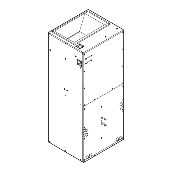
2.6. About unit of the length 3.2. Indoor unit dimensions This product is different from other Fujitsu General products and it is designed with United States customary unit. Metric units are provided for reference. When the exact dimensions and tolerances are required, refer to the United States customary units. -
Page 5: Clearance And Return Air Requirements
3.3. Clearance and return air requirements 3.4. Airfl ow direction and preparation before installation Arrangement: Location Unit is shipped from the factory arranged to be installed in an upflow or horizontal right to left Access for servicing is an important factor in the location of any indoor unit. Provide a airflow position. - Page 6 (1) Remove the panels. (3) Cut the cable tie that holds the room temperature thermistor inside the heat exchanger (access from the intake port), and remove the room temperature thermistor from the * Do not lose the grommets that protects the refrigerant pipes. heat exchanger.
- Page 7 (6) Remove the fasteners on the drain pan for horizontal installation. (2 places) (9) Move the drain pan for horizontal installation to the right side of the heat exchanger. Then, remove the frame on the suction side of the unit. Then reinstall the heat exchanger and fix it with screws.
- Page 8 (11) Insert the thermistors removed in step (4) into the thermistor holder at the position (12) Reinstall the solenoid coil removed in step (5) in the orientation shown in the figure. shown in the figure, and fix them with the fixing springs. Then, clamp the cables with the (*Be sure to match the snap fittings on the solenoid coil and armature.
- Page 9 ARUX12 ARUX60 Bind the cables to the pipe Bind the cables to the pipe Bind the cables together Bind the cables together ARUX18/24 Bind the cables to the pipe Bind the cable to the pipe (14) Finish the cables. CAUTION Make sure that the cables are not tensioned.
-
Page 10: Installing The Unit
3.5.4 Mounting the duct 3.5. Installing the unit CAUTION WARNING To prevent people from touching the parts inside the unit, be sure to install grilles on the inlet and outlet ports. The grilles must be designed in such a way that cannot be removed Install the air conditioner in a location which can withstand a load of at least 5 times the without tools. -
Page 11: Pipe Requirement
(2) First, pass the grommet (for the liquid pipe) through the connection pipe (liquid). 4.2. Pipe requirement Protect the periphery of brazing area by wet cloth, etc. and then braze the pipes. : Protect these areas with wet cloth, etc. CAUTION Refer to the installation manual of the outdoor unit for description of the length of connect- ing pipe or for difference of its elevation. -
Page 12: Installing Drain Pipes
4.4. Installing drain pipes CAUTION Ground (Earth) the unit. The drain pan has two 3/4 in NPT (National pipe thread) female primary and two secondary Do not connect the ground (earth) cable to a gas pipe, water pipe, lightning rod, or a connections (left or right hand). -
Page 13: Wiring Method
B. For strand wiring 5.2. Wiring method (1) Use ring terminals with insulating sleeves as shown in the figure below to connect to the terminal block. Example (2) Securely clamp the ring terminals to the cables using an appropriate tool so that the Outdoor unit or RB unit (*1) cables do not come loose. -
Page 14: Connection Of Wiring
5.4.3 Control entry connections 5.4. Connection of wiring CAUTION 5.4.1 Entries position Do not pass the power supply cable through the control entry. CAUTION Cable tie (small; accessories) To protect the cable insulation after opening a knockout hole, remove any burrs from the Remote controller cables Transmission cables connect edge of the hole. -
Page 15: Optional Parts Wiring
5.6.3 Connection methods 5.6. Optional parts wiring Wire modification for External IMPORTANT: 5.6.1 Connector and DIP switch position input/output wire Be sure to insulate the connection between the (1) Remove insulation from wire at- wires. CAUTION tached to wire kit connector. Locally Wire kit connector (2) Remove insulation from field... - Page 16 Input select When connected to dry contact terminals of multiple indoor units with a connected unit, insulate each indoor unit with relay, etc. as shown on below example. Use either one of these types of terminal according to the application. (Both types of termi- nals cannot be used simultaneously.) Controller PCB ●...
-
Page 17: Heater Connection
● Forced thermostat off function 5.8.1 Wiring diagram of heaters [“Edge” input only] Breaker 1: Ground Fault Equipment Breaker (GFEB) Breaker 2: Maximum Circuit Breaker (MAX. CKT. BKR) Function Connector Input signal Command setting NOTE: For details of the connection terminal functions, refer to the Design & Technical manual. OFF →... -
Page 18: Remote Sensor (Optional Parts)
• If working in an environ- Table A 5.9. Remote sensor (optional parts) ment where the wireless Rotary switch Rotary switch remote controller can Address Address For the installation method, please refer to the installation manual of the Remote sensor. setting setting be used, the addresses... - Page 19 Function details Function Function Setting number Default Details number Function Function Setting number Default Details Auxiliary number heater Adjust the filter cleaning interval noti- 00 Standard control 1 Filter indica- fication. If the notification is too early, 01 Longer Auxiliary tor interval change to setting 01.
-
Page 20: Test Run
Temperature conditions when the external heater is ON/OFF Function Function Setting number Default Details number Temperature (t) = Room temperature - set temperature 00 Disable Set value of function: 61 Standby 01 1 minutes time for 01 to 09 auxiliary Sets the standby time until the 02 2 minutes equipment... -
Page 21: Error Codes
9. ERROR CODES If you use a wired type remote controller, error codes will appear on the remote controller display. If you use a wireless remote controller, the lamp on the photodetector unit will output error codes by way of blinking patterns. Refer to the following table for lamp blinking patterns and error codes.
Need help?
Do you have a question about the AIRSTAGE ARUX12TLAV2 and is the answer not in the manual?
Questions and answers