
Subscribe to Our Youtube Channel
Related Manuals for EWM Cool 50 MPW50


Summary of Contents for EWM Cool 50 MPW50
- Page 1 Operating instructions Air-cooling units for water-cooled welding torches Cool 50 MPW50 099-008818-EW501 Observe additional system documents! 30.05.2018...
- Page 2 +49 2680 181-0. A list of authorised sales partners can be found at www.ewm-group.com/en/specialist-dealers. Liability relating to the operation of this equipment is restricted solely to the function of the equipment.
-
Page 3: Table Of Contents
Checklist for rectifying faults ......................18 Vent coolant circuit ........................19 Fixing the pump shaft (coolant circuit) ..................19 8 Technical data ............................21 Cool 50 MPW50 ........................... 21 9 Accessories ............................22 General accessories ........................22 10 Appendix A ............................23 10.1 Searching for a dealer ......................... -
Page 4: For Your Safety
For your safety Notes on the use of these operating instructions For your safety Notes on the use of these operating instructions DANGER Working or operating procedures which must be closely observed to prevent imminent serious and even fatal injuries. •... -
Page 5: Explanation Of Icons
For your safety Explanation of icons Explanation of icons Symbol Description Symbol Description Indicates technical aspects which the Activate and release / Tap / Tip user must observe. Switch off machine Release Switch on machine Press and hold Switch Incorrect / Invalid Turn Numerical value –... -
Page 6: Part Of The Complete Documentation
For your safety Part of the complete documentation Part of the complete documentation These operating instructions are part of the complete documentation and valid only in combination with all other parts of these instructions! Read and observe the operating instructions for all system components, especially the safety instructions! The illustration shows a general example of a welding system. -
Page 7: Intended Use
3.2.1 Warranty For more information refer to the "Warranty registration" brochure supplied and our information regarding warranty, maintenance and testing at www.ewm-group.com! 3.2.2 Declaration of Conformity The labelled product complies with the following EC directives in terms of its design and construction: •... -
Page 8: Machine Description - Quick Overview
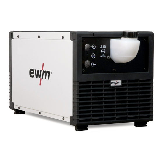
Machine description – quick overview Front view Machine description – quick overview Front view Figure 4-1 Item Symbol Description Screw connector Connects cooling module and welding machine Machine feet Cooling air inlet Coolant tank > see 5.2.3 chapter Coolant tank cap 099-008818-EW501 30.05.2018... -
Page 9: Rear View
Machine description – quick overview Rear view Rear view Figure 4-2 Item Symbol Description Quick connect coupling, red Coolant return from the welding torch Quick connect coupling, blue Coolant supply to the welding torch Automatic cut-out of coolant pump key button press to reset a triggered fuse Cooling air outlet Connector plug, 8-pole... -
Page 10: Design And Function
Design and function Assembly/disassembly Design and function WARNING Risk of injury from electrical voltage! Contact with live parts, e.g. power connections, can be fatal! • Observe the safety information on the first pages of the operating instructions! • Commissioning must be carried out by persons who are specifically trained in handling power sources! •... -
Page 11: Coolant Line Connections
Design and function Transport and installation 5.1.2 Coolant line connections Figure 5-2 Item Symbol Description Power source Hose bridge Coolant-connection lead (red/blue) The item described in the following is part of the machine´s scope of delivery. • Lock connecting nipples of the cooling water tubes into the corresponding quick connect couplings: Return line red to quick connect coupling, red (coolant return) and supply line blue to quick connect coupling, blue (coolant supply). -
Page 12: In Operation
Design and function Transport and installation 5.2.2.1 In operation Temperature range of the ambient air: • -25 °C to +40 °C (-13 F to 104 F) Relative humidity: • up to 50 % at 40 °C (104 F) • up to 90 % at 20 °C (68 F) 5.2.2.2 Transport and storage Storage in a closed room, temperature range of the ambient air:... -
Page 13: Maximal Hose Package Length
All information relates to the total hose package length of the complete welding system and presents exemplary configurations (of components of the EWM product portfolio with standard lengths). A straight kink-free installation is to be ensured, taking into account the max. delivery height. -
Page 14: Adding Coolant
Design and function Functional characteristics 5.3.1 Adding coolant If the cooling system is empty or only insufficiently filled with coolant, the coolant pump is automatically switched off after approx. one minute (protection against destruction). At the same time, the welding data display signals the lack of coolant or low coolant level. •... -
Page 15: Maintenance, Care And Disposal
Maintenance, care and disposal General Maintenance, care and disposal General DANGER Risk of injury due to electrical voltage after switching off! Working on an open machine can lead to fatal injuries! Capacitors are loaded with electrical voltage during operation. Voltage remains present for up to four minutes after the mains plug is removed. -
Page 16: Maintenance Work, Intervals
A periodic test according to IEC 60974-4 "Periodic inspection and test" has to be carried out. In addition to the regulations on testing given here, the relevant local laws and regulations must also be observed. For more information refer to the "Warranty registration" brochure supplied and our information regarding warranty, maintenance and testing at www.ewm-group.com! 099-008818-EW501 30.05.2018... -
Page 17: Disposing Of Equipment
• Information about returning used equipment or about collections can be obtained from the respective municipal administration office. • In addition to this, returns are also possible throughout Europe via EWM sales partners. 099-008818-EW501 30.05.2018... -
Page 18: Rectifying Faults
Rectifying faults Checklist for rectifying faults Rectifying faults All products are subject to rigorous production checks and final checks. If, despite this, something fails to work at any time, please check the product using the following flowchart. If none of the fault rectification procedures described leads to the correct functioning of the product, please inform your authorised dealer. -
Page 19: Vent Coolant Circuit
Rectifying faults Vent coolant circuit Vent coolant circuit To vent the cooling system always use the blue coolant connection, which is located as deep as possible inside the system (close to the coolant tank)! Figure 7-1 Fixing the pump shaft (coolant circuit) WARNING Do not carry out any unauthorised repairs or modifications! To avoid injury and equipment damage, the unit must only be repaired or modified by... - Page 20 Rectifying faults Fixing the pump shaft (coolant circuit) Continuing non-use and impurities in the coolant may result in the the coolant pump not being in proper working order. Figure 7-2 • Switch off machine at the main switch. • Insert a plain slot screwdriver with a maximum tip width of 6.5 mm through the maintenance opening and place in the centre of the pump shaft.
-
Page 21: Technical Data
Technical data Cool 50 MPW50 Technical data Technical data limit values The limit values determination from technical data is calculated taking account of the combined system as a whole (cooling unit and welding machine). Cool 50 MPW50 Supply voltage (from the welding machine) -
Page 22: Accessories
Accessories General accessories Accessories General accessories Type Designation Item no. TYP 1 Frost protection tester 094-014499-00000 KF 23E-10 Coolant (-10 °C), 9.3 l 094-000530-00000 KF 23E-200 Coolant (-10 °C), 200 litres 094-000530-00001 099-008818-EW501 30.05.2018... -
Page 23: Searching For A Dealer
Appendix A Searching for a dealer Appendix A 10.1 Searching for a dealer Sales & service parteners www.ewm-group.com/en/specialist-dealers "More than 400 EWM sales partners worldwide" 099-008818-EW501 30.05.2018...
Need help?
Do you have a question about the Cool 50 MPW50 and is the answer not in the manual?
Questions and answers