
Subscribe to Our Youtube Channel
Related Manuals for Walchem EH Series


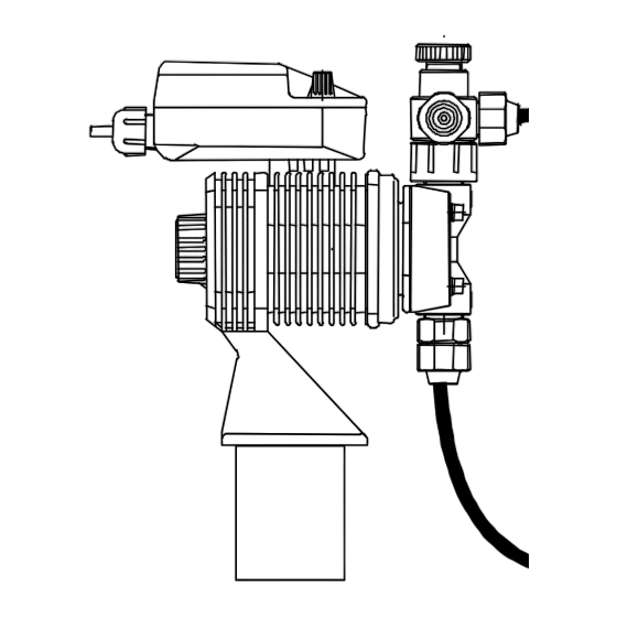
Summary of Contents for Walchem EH Series
- Page 1 EH & EZ Series Electronic Metering Pump Instruction Manual Five Boynton Road Hopping Brook Park Holliston, MA 01746 USA TEL 508-429-1110 FAX 508-429-7433 WEBSITE: www.walchem.com...
- Page 2 WALCHEM Corporation and for the purposes disclosed in writing at the time purchased, if any. WALCHEM Corporation’s liability under this warranty shall be limited to replacement or repair, F.O.B.
-
Page 3: Table Of Contents
TABLE OF CONTENTS Thank you for choosing a Walchem EH or EZ Series metering pump. This instruction manual deals with the correct installation, operation, maintenance and troubleshooting procedures for the EHB, EHC and EZ model metering pumps. Please read through it carefully to ensure the optimum performance, safety and service of your pump. -
Page 4: Introduction
All tubing must be securely attached to the fittings prior to starting the pump (see Section 2.3). Only use Walchem tubing with your pump. Tubing should be shielded to prevent possible injury in case of rupture or damage. UV resistant tubing should be used if the tubing is exposed to UV light. -
Page 5: Model Code
Auto Air Vent Valve supplied in place of manual air vent valve. Available for EZ and EH Series in B10, B15, C15 and C20 sizes with – VC liquid ends only. High Pressure Head available only for PC/PE liquid ends. Available... -
Page 6: Specifications
Specifications Electrical 50/60 Hz, single phase EHB/EZB 115 VAC±10% 0.9 Amp max. 16 watt avg. 230 VAC±10% 0.4 Amp max. 16 watt avg. EHC/EZC 115 VAC±10% 1.4 Amp max. 24 watt avg. 230 VAC±10% 0.6 Amp max. 24 watt avg. Operating Conditions Ambient temperature 32°F to 122°F (0°C to 50°C) -
Page 7: Dimensions
Dimensions EH Models with thermoplastic liquid ends and air vent valves EHB Model shown for reference DISCHARGE VENT SUCTION P&Q Model TUBIN 7.48 1.46 7.24 5.91 (9.07) 3/8 OD 2.64 1.42 0.83 3.54 (3.01) 0.20 {7.56} 1.02 3.94 [6.13] {7.72} 1/4 ID [1.83] [8.40]... - Page 8 EH-FC Models without an air vent valve EHB Model Shown for reference P&Q Model TUBING 7.07 6.46 3/8 OD 2.64 1.38 0.83 3.54 0.47 0.20 6.04 1.04 3.94 1/4 ID (7.56) (6.81) 7.07 6.81 1/2 OD 2.64 1.57 0.83 3.54 0.63 0.20 6.77...
- Page 9 Models with stainless steel liquid end materials EHB Model Shown for reference DISCHARGE OD ¼" SUCTION P&Q Model TUBING 7.07 7.38 2.64 1.38 0.83 3.54 1.34 0.20 5.75 1.34 ¼” NPTF 3.94 (7.56) (7.74) 7.46 8.29 3.82 1.22 0.67 3.94 1.34 0.20 6.14...
- Page 10 Models with thermoplastic liquid end materials EZB Model Shown for reference All dimensions in inches P & Q Model TUBING 1.46 7.44 5.91 7.24 3.21 0.87 0.08 3.54 (3.03) 0.20 1.02 (9.53) 3/8” O.D. 3.94 [6.11] [8.39] [1.83] [7.81] 3.21 0.87 0.08 3.54...
-
Page 11: Installation
INSTALLATION Unpacking Open the shipping carton and inspect contents for damage. If any items are missing or damaged contact your local distributor. Pumps are pre-primed with water at the factory. If the application is not compatible with water, drain and dry before use. Be sure to remove caps from fittings before attaching tubing. - Page 12 Figure 1 Figure 2 Figure 3 Flooded Suction Shelf Mount Tank Mount Coupling Nut Injection (Air Vent Valve) Valve Point of Injection Coupling Nut Return Line Pipe Tubing Straightener Air Gap (user supplied) Coupling Nut Foot Valve Figure 4 Connecting Tubing...
-
Page 13: Supply Tubing
Supply Tubing The supply tubing run should be as short as possible. For flooded suction mounting, install a shut-off valve with an appropriate tubing connector at the tank outlet. Cut a length of tubing from the coil supplied and install between the shut-off valve and the pump inlet fitting. -
Page 14: Discharge Tubing
Discharge Tubing Cut a length of tubing long enough to go from the pump to the application (injection) point. Additional tubing can be ordered from your distributor. Avoid sharp turns or bends and hot surfaces. Routing tubing through rigid pipe such as PVC pipe is recommended for long runs and/or as protective shielding against corrosive chemicals. -
Page 15: Electrical
However, the back pressure by the injection valve can vary and the valve does NOT act as an anti-siphon valve. If siphoning is a possibility, or if pumping downhill into open atmosphere (open tank), a Walchem MultiFunction valve or a separate back pressure/anti-siphon valve must be installed. -
Page 16: Operation
OPERATION Priming Install the pump as described above. With the pump turned on, set stroke length at 100% and frequency at 100%. If the pump is equipped with an air vent valve, open the knob 1/2 turn. Liquid should move through the suction tubing and into the pump head. -
Page 17: Calibration
Calibration If exact output calibration is required, first prime and adjust the pump as above. Then connect a calibration column to the suction side of the pump. Turn the pump on for one minute and read the amount of liquid pumped from the column. - Page 18 B. Pumps using the ‘Y’ Control Module The EH-Y Series is able to operate in both digital and analog external modes. An external stop function is also available. STOP indicator. Visible Display/Keypad Overview when the pump is stopped Alpha/numeric display. Indicates via external signal.
- Page 19 EH-Y Quick Reference Guide Start/Stop Key External Key PRESS: FROM: Run in manual mode WAIT MODE Decrease frequency (1 to 360 SPM) Increase frequency (1 to 360 SPM) Run in ternal mode external mode external values RUNNING IN Decrease frequency (1 to 360 SPM) MANUAL MODE Increase frequency (1 to 360 SPM) WAIT...
- Page 20 Digital Mode In digital mode, the pump accepts a non-powered pulse signal (contact closure type or solid state device) from a flowmeter or other instrument. The pump can be set to divide pulses by a factor of 1 to 999; or in multiply mode, 1 input pulse can produce 1 to 999 pump strokes.
- Page 21 For Y-Control Modules: Connection is the same as above, except the POSITIVE terminal is Terminal # 6 and the GND is Terminal #8 Sensor Power The control circuit of the Y Module has the ability to provide 12 VDC at up to 20 mA to power a Hall effect sensor or similar device.
- Page 22 Analog Mode In analog mode the pump will accept a milliamp signal and produce a pump speed proportional to the signal level received. The input resistance of this signal is 250 Ω . The pump’s response can be fine-tuned by variable set points to meet system requirements.
- Page 23 Settings The pump’s response to a 4 to 20 milliampere signal can be adjusted to meet almost any need. The adjustment is done by selecting two points. A signal level and a pump speed are entered for each point. These two points determine a straight line and the pump speed resulting from any given signal will be defined by that line.
- Page 24 Press EXT to operate the pump in external mode. The pump speed will now be determined by the level of the milliamp signal as shown in the graph. The stroke length can be adjusted manually to set the volume pumped per stroke. INPUT SIGNAL, mA...
- Page 25 C. Pumps using the ‘T’ Control Module The EZB-Timer Series is able to operate in Daily, Weekly and 2-Week modes. An external stop input and 12VDC output are also available. Display/Keypad Overview Alpha/numeric display. Indicates WAIT mode, stroke frequency, NUM indicator. Becomes time or pump on-time.
- Page 26 EZ-T Quick Reference Guide MODE Mode Key Select Key PRESS: FROM: TIMER RUN MODE Move to WAIT menu MENU MODE Move to MANUAL menu WAIT MENU Move to TIME / DATE setting menu (Hold for 3 seconds) Move to TIMER programming menu HOUR Move to TIMER MODE selection menu Move to TIMER RUN mode (shows TIME)
- Page 27 Programming and Timer Use CAUTION! Before use, check the time and date. Set to the local time and date before programming. Incorrect time/date can result in incorrect operation. 1. Manual Operation From the WAIT menu, pressing the MODE key will enter the manual mode. Pressing SEL will toggle the pump on and off manually.
-
Page 28: Stop Function
the 2 week. All programming functions are the same and SEL will scroll through each setting. Pressing MODE will go back to the WAIT menu at any point in the programming. From the WAIT mode, pressing MODE will move to the MANUAL menu. Check to make sure that the pump speed is set at the rate desired during the timed operations. -
Page 29: Auto Air Vent Valve Operation
Auto Air Vent Valve Operation The Auto Air Vent Valve is an option on select EH and EZ pumps and replaces the standard Manual Air Vent Valve when ordered. It is used primarily in applications where gassing is a problem and pumps can lose prime. Unlike the Manual Air Vent Valve, the Auto Air Vent Valve constantly bleeds a controlled amount of volume out of the “Air”... -
Page 30: Multifunction Valve Operation
MultiFunction Valve Operation The MultiFunction Valve is optional on select EH and EZ pumps and replaces the standard Manual Air Vent Valve when ordered. It integrates the air venting/bleeding functions with a back pressure and anti-siphon valve. Air Vent / Bleed Function 1. -
Page 31: Maintenance
MAINTENANCE CAUTION: Before working on the pump, disconnect the power cord, depressurize the discharge tubing and drain or flush any residual liquid from the pump head and valves. Always wear protective gear when working around chemicals. Diaphragm Replacement Disconnect AC power to the pump and disconnect the suction tubing, discharge tubing, and air vent tubing. -
Page 32: Exploded View & Parts Guide
EXPLODED VIEW & PARTS GUIDE PVC/GFRPP Liquid End Exploded View #1 For EH and EZ pump model sizes 10, 15, and 20 Manual Air Vent Valve (Standard) Auto Air Vent Valve (Optional) Item #1 EH Heads (Qty 1) Part No Description Size Liquid End Mat’l... - Page 33 PVC/GFRPP Liquid End Exploded View #1 Components Item Part No Description Size Liquid End Mtl Series EH0400 Housing, Valve, 3/8 PVC 10, 15, 20 VC, VE, VF EH, EZ EH0418 Housing, Valve, 3/8 GFRPP 10, 15, 20 PC, PE EH, EZ EH0401 Nut, Coupling, 3/8 PVC 10, 15, 20...
- Page 34 PVC/GFRPP Liquid End Exploded View #2 For EH and EZ pump model sizes 30 and 35 Entire Head Assembly Valve Cartridge Air Vent Valve Part numbers for these assemblies are on Page 40...
- Page 35 PVC/GFRPP Liquid End Exploded View #2 Components Item Part No Description Size Liquid End Mtl Series EH0329 Head, H30 GFRPP PC, PE EH0113 Head, H30 PVC VC, VE, VF EH0585 Head, Z30, GFRPP PC, PE EH0570 Head, Z30, PVC VC, VE, VF EH0336 Head, H35 GFRPP PC, PE...
- Page 36 PVDF Liquid End Exploded View #3 For all PVDF EH and EZ Pump Models TC Only TC Only FC Only 30 and 10, 15, and All sizes Entire Head Assembly 14 (FC only) Valve Cartridge Air Vent Valve Part numbers for these assemblies are on Page 40 14 (FC only)
- Page 37 PVDF Liquid End Exploded View #3 Components Item Part No Description Size Liquid End Mtl Part No Description Size Liquid End Mtl EH Heads EZ Heads EH0608 Z10, PVDF FC, TC EH0337 H10, PVDF FC, TC EH0609 Z15, PVDF FC, TC EH0814 H15, PVDF FC, TC...
- Page 38 S.S. Liquid End Exploded View #4 For all Stainless Steel (SH) EHB/C Pump Models Item Part No Description Size EH0358 Head, H10 SS EH0372 Head, H20 SS EH0376 Head, H30 SS EH0383 Head, H35 SS EH0429 Housing, Valve, .188 & .250 SS 10, 20 EH0433 Housing, Valve, .375 1/4 NPTF SS...
- Page 39 Accessories (Not Shown) Part No. Description Size Liquid End Mtl Series E90001 Valve, Injection 3/8 10, 15, 20 EH, EZ E90002 Valve, Injection 3/8 10, 15, 20 VE, VF EH, EZ E90003 Valve, Injection, 3/8 10, 15, 20 EH, EZ E90004 Valve, Injection, 3/8 10, 15, 20...
- Page 40 Drive and Control Module Exploded View B: R-CONTROL MODULE Y-CONTROL MODULE EH Drives EZ Drives A: DRIVE UNIT Drive Unit R-Control Module Y-Control Module Part numbers for these assemblies are on Page 40...
- Page 41 Drive and Control Module Exploded View Drive and Control Components Item Part No. Description Series EH1209 Label, Control Module Cover EH-Y EH1213 Gasket, Terminal Box EH-Y EH1212 Terminal Box EH-Y EH0261 Gasket, M3 x 35 Bolt EH-R, EH-Y, EZ-D EH0202 Grommet, Cord EH-R, EH-Y, EZ-D EH0204...
- Page 42 EHB, EHC Air Vent Valve Control Assembly Module Head Assembly Drive Unit Valve Cartridge (not shown in this view) EZB, EZC Key letters: Drive Unit Control Module Valve Cartridge Head Assembly Air Vent Valve Assembly Notes: To get the correct model or part number, enter a “C” or “B” into the blank space “__”...
- Page 43 Pump Model Head Assembly/Spare Parts Kit* Drive Control Liquid End Material Unit Module EHB10R1- HB10-1 EHC-B11UPR H10PC H10PE H10VC H10VE H10VF H10TC H10FC H10SH EHB10R2- HB10-2 EHC-B23UPR EH__15R1- H__15-1 EHC-__11UPR H15PC H15PE H15VC H15VE H15VF H15TC H15FC EH__15R2- H__15-2 EHC-__23UPR EH__20R1- H__20-1 EHC-__11UPR...
-
Page 44: Troubleshooting
TROUBLESHOOTING CAUTION: Before working on the pump, disconnect the power cord, depressurize the discharge tubing and drain or flush any residual liquid from the pump head and valves, using proper chemical handling techniques. Problem Possible Cause Corrective Action Pump does not start Faulty wiring Correct wiring Improper voltage... -
Page 45: Service Policy
Torque: 19 lb-in (2.16 N-m) Diaphragm is damaged Replace diaphragm O-ring or valve gasket Install o-ring or valve gasket missing SERVICE POLICY The EH and EZ Series electronic metering pumps have a 2-year warranty. Contact your Walchem distributor for service. - Page 46 Notes...
- Page 47 Five Boynton Road Hopping Brook Park Holliston, MA 01746 USA TEL 508-429-1110 FAX 508-429-7433 WEBSITE: www.walchem.com...
Need help?
Do you have a question about the EH Series and is the answer not in the manual?
Questions and answers