
Related Manuals for Chinowing T26

Summary of Contents for Chinowing T26
- Page 1 Handheld Ground Control Station User Manual 2022.1 V 1.0.1 www.chinowing.com...
-
Page 2: Table Of Contents
7.1 V21 Receiver Connection Instruction ........14 9. T26 Internal Network Card Use ............16 8. The use of Serial Port Data Link of T26 and Receiver T26 ....15 10. Video Display ..................19 10.1 Display the Video in Mission Planner ........19 11. -
Page 3: Product Precautions
2. Disclaimer Thank you for purchasing the T26 hand-held remote-control station. Please use it in accordance with local radio control regulations and read this statement carefully before using it. Once used, it shall be deemed to endorse and accept all... -
Page 4: Installation Note
2.1 Installation Note 1) Be sure to use the spare parts provided by Chinowing. 2) Be sure to install the antennas before power-on to avoid the damage to the circuit. -
Page 5: Product Introduction
Stop using it when the battery is too low. Don't rely on the device's low-power alarm, which is only a precaution and tells you when to charge. T26 can work continuously for 8hs with full battery capacity and takes about4hs to be fully charged. - Page 6 Accessories (Power for receiver, DC 7.4-12v, Power supply cable*1 (8.4v adapter) Charger*1 lithium battery 2S-3S) Receiver Upgrading (User for connecting other device by LAN-to-4Pin wire*1 (Used for receiver firmware upgrading and configuration line LAN port) parameters setting) www.chinowing.com...
-
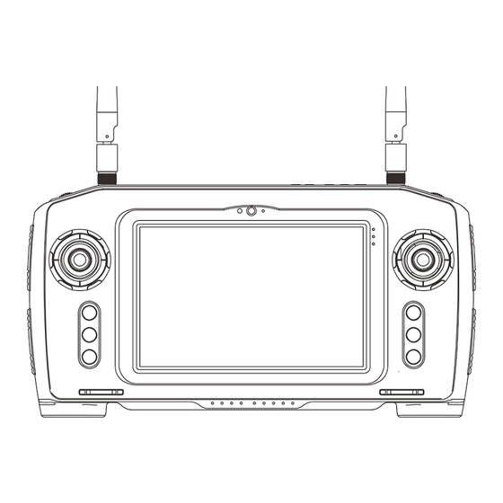
Page 7: Product Instruction
Antenna*4 GH 3pin*2 GH 4pin*1 5. Product Instruction 5.1 T26 GCS www.chinowing.com... - Page 8 18. Rx data receiving indicator, Rx continuously ON indicating in the receiving status 19. RC/computer charging port, adapter DC16V 4A 20. 4 buttons, corresponding to F7-F10 21. Battery jar lock catch 22. SIM/SD card slot, used for installing micro SIM card or micro SD card www.chinowing.com...
-
Page 9: V21 Receiver
③ Signal strength indicator: S3 ON, signal is weak; S3 and S2 ON, signal is moderate; S3, S2 and S1 ON, signal is strong. ④SET button: used for firmware upgrading, serial port baud rate setting, Failsafe protection settings Side view ①TTL port: full duplex serial port ②S-BUS1port: SBUS input(ground unit);SBUS output(airborne unit) www.chinowing.com... - Page 10 Ground unit: SBUS2 indicator will flicker when there is data input of SBUS2. Airborne unit: SBUS2 indicator will flicker when there is data output of SBUS2. LAN port: for video input or output USB port: debugging interface, for video output www.chinowing.com...
-
Page 11: Remote Control Operation
Please pay attention to the power button, the computer power indicator and the remote control power indications (25%, 50%, 75%, 100%) during the switching on and off of the T26. The computer and the remote control use the same button to control the switching on and off of the T26. -
Page 12: Remote Control Charging
T26 remote control is used with 6800mAh lithium battery. The computer is with built-in quick release lithium ion battery 3220mAH. The RC data link module can work normally with in 1W power. T26 can work about 8hs with fully charged battery. If the power indicator shows low battery power, please stop flying and recharge the T26 in time. - Page 13 Indicators are normal, the buzzer beeps Idle alarm of remote control continuously 6.3.2 V21 Receiver Indicators Instruction Flashing There is data transmitting Indicator Status Define There is no data transmitting Flashing There is data receiving There is no data receiving www.chinowing.com...
-
Page 14: V21 Video Link Module Operation And Use
All parameters of the remote control and receiver module have been configured well at the factory and can be used directly. If the user wants to modify the serial port baud rate and the IP address of the LAN port, please refer to the corresponding chapter. www.chinowing.com... -
Page 15: The Use Of Serial Port Data Link Of T26 And Receiver T26
Baud rate: 115200; Eight data bits; One stop bit; No Parity Serial Port Parameters 8. The use of Serial Port Data Link of T26 and Receiver T26 Default baud rate of serial port: 115200. Pls follow the below steps to connect flight control and GCS software. -
Page 16: T26 Internal Network Card Use
The V21 data link is already connected to the LAN port of the internal module of the T26 remote control and can be used directly. The receiver V21 can be connected to a LAN camera by using a LAN-to-4pin cable. After finishing the setting of the IP address, the video can be transmitted. - Page 17 1. The IP addresses of T26 and V21 are all set to the same network segment. Airborne unit: 192.168.168.2 Ground unit: 192.168.168.1 2. When connecting IPC devices or other network devices to the LAN port of the airborne unit, the IP addresses of V21 and T26 can be ignored. Just set the IP camera to the same network segment as the mobile devices connected to T26.
- Page 18 For example: camera IP is 192.168.167.10, set the local IP to192.168.167.xxx(0~25, expect 10). After the modification, click OK when finishing the modification. Use pull streaming software such as VLC media player to capture and play back the video data. www.chinowing.com...
-
Page 19: Video Display
! decodebin ! videoconvert ! video/x-raw,format=BGRA ! appsink name=outsink 5.For the first time usage, download the relevant software package and wait for the download to complete. Restart software. 6.After finishing steps 1-5, the camera video source can be obtained. www.chinowing.com... - Page 20 www.chinowing.com...
-
Page 21: Display Image In Qgc Software
Currently, GQC supports video hardware decoding to reduce the latency. 1. Change the video encoding mode to H.264 2. Open QGC software, Click general and find video. VIDEO source chooses RTSP VIDEO STREAM; in RTSP URL, input RTSP: / / 192.168.168.13 / stream0 www.chinowing.com... -
Page 22: V21 Video&Data Link Configuration
② Set the local IP to static IP in the PC network sharing centre, the IP is in the same network segment as the IP of the airborne unit, for example: 192.168.168.15. www.chinowing.com... - Page 23 If the login does not respond or if you are prompted with "This browser does not support ActiveObject", please download another browser (e.g. Sogou or Microsoft Edge) or update your browser version and try again. ⑤ After successful login, the module configuration interface appears. www.chinowing.com...
- Page 24 The modification of power can be made in <Building Chain Management>. For example, changing "-10dbm" to "10dbm" in the power range of <-40db ~ 25dbm>. www.chinowing.com...
- Page 25 If there is not any question, it is not recommended to modify it. If it is needed, the airborne unit setting is valid, <1D4U> means the ratio of downlink and uplink is 1:4. www.chinowing.com...
- Page 26 The third parameter is the power, which ranges from <40db ~ 25dbm>. As show below: ⑥<Equipment Information> shows the current module version number. Please make sure that the version number of the airborne unit and ground unit is the same. www.chinowing.com...
-
Page 27: Hid Controller Instruction
12.HID Controller Instruction In order to meet more requirement of the customers, we integrated all channels into HID device controller in T26. If your remote control does not find HID device controller, pls refer to the below steps to check it: 1. - Page 28 3. Click the right mouse button and select "Game Controller Settings". Select "chinowing HZY-JOY", click on properties and the user will see the individual channels in the test bar. When you move the joystick, the status of the corresponding channel will change. The X/Y axis, Z axis, X-rotation, Y-rotation, Z-...
-
Page 29: Firmware Upgrading Operation Steps
Pls use the firmware upgrade tool to upgrade the firmware of the remote control and the receiver separately. 13.1 T26 Remote Control Firmware Upgrade 1.Click on the official website to download the firmware, select the appropriate version of the firmware and save it locally. - Page 30 4.At this time, the serial port of firmware upgrade tool has been connected, and the current hardware, firmware and other information of the remote control are displayed, as shown in the figure below: Version no. Instruction: TLC16-0.1.1. TLC16 stands for T26 remote control, 0.1.1is firmware no.. www.chinowing.com...
-
Page 31: V21 Receiver Firmware Upgrade
2.Use the matching configuration cable to connect to the V21 TTL port (White-TX, Black-G, Green-RX), press and hold the set button to power up, and release the button when the RX and TX indicators are always ON. Open the upgrade software www.chinowing.com... - Page 32 1min. A corresponding message will pop up, representing entry into upgrade mode. 3. Open Upgrading software 4.Click , open the right downloaded firmware. If correct, it will show that the firmware file identification is complete. 5.Click , Until the firmware write is completed, the upgrade is successful. www.chinowing.com...
-
Page 33: Common Questions
3.The receiver SBUS has signal output, but the serial port cannot be connected, or the transmission signal is garbled Please check that the baud rate of the serial port of the remote control and the receiver are the same; and set them the same www.chinowing.com... - Page 34 Whether the module versions are the same. c. Whether the RF parameters are consistent. d. Check that other equipment, equipment connection cables and computer interfaces are normal. e. Check the image streaming software settings or change to another streaming software to play the video. www.chinowing.com...
Need help?
Do you have a question about the T26 and is the answer not in the manual?
Questions and answers