Table of Contents
Advertisement
Quick Links
Advertisement
Table of Contents

Related Manuals for LTB MNL X00 Series


Summary of Contents for LTB MNL X00 Series
- Page 1 LIGHT. PRECISION. ANALYTICS. Nitrogen Laser MNL 100 / MNL X00 Operating Manual LTB Lasertechnik Berlin GmbH Am Studio 2c, 12489 Berlin, Germany Phone: +49 30 912075-100 Fax: +49 30 912075-199 info@ltb-berlin.de Oct. 2022 www.ltb-berlin.de Rev. 10...
- Page 2 Dear customers Dear customers With the purchase of an OEM laser from the MNL 100 / MNL X00 series, you have selected a state-of-the-art Nitrogen Laser. This laser satisfies the sophisticated needs and demanding goals of various applications within the industry.
-
Page 3: Table Of Contents
Operating Manual MNL 100 / MNL X00 Contents Contents About this Operating Manual ........................ 5 Contact manufacturer, Imprint, Copyright ..................5 Safety precautions ..........................6 Invisible laser radiation ........................6 High voltage up to 12 kV ........................ 7 Dangerous gases ........................... 7 Liability, Replacement parts ...................... - Page 4 Operating Manual MNL 100 / MNL X00 Contents 6.2.1 Calibration of the energy monitor ..................25 Attenuator module (in connection with energy monitor) .............. 26 Fiber coupling ..........................27 Optical trigger with electrical output ..................... 27 OEM – Applications ..........................28 AUTOMODE operation ........................
-
Page 5: About This Operating Manual
Operating Manual MNL 100 / MNL X00 1 About this Operating Manual 1 About this Operating Manual For safe and proper use of the product, read this manual carefully before use and act accordingly. Keep this manual for future reference. This document is available as print media / pdf on request. -
Page 6: Safety Precautions
Operating Manual MNL 100 / MNL X00 2 Safety precautions 2 Safety precautions Please note: the laser source is an OEM device which is used for integration only. MNL Lasers are 3B class lasers (IEC 60825-1) Improper treatment and operation of the laser can cause damage to your health. Please follow carefully all the instructions in this manual. -
Page 7: High Voltage Up To 12 Kv
Operating Manual MNL 100 / MNL X00 2 Safety precautions Always close the beam shutter when the laser is not in operation. Please observe that there are no reflecting materials in the beam path by which the laser beam could unintentionally be directed towards persons or sensitive materials. -
Page 8: System Requirements
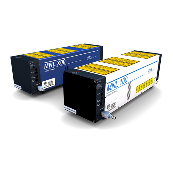
Operating Manual MNL 100 / MNL X00 3 System requirements 3 System requirements 3.1 Place and way of installation Figure 2: MNL laser The laser is intended for indoor use. The laser must be operated and stored in a dry, dust-poor and well- ventilated area. -
Page 9: Electric Requirements
For integrating the MNL 100 / MNL X00 in a system control, the interfaces of the MNL 100 / MNL X00 are described in detail in the Interface Manual. Alternatively to the operation via the optical PC interface, the lasers of the MNL 100 / MNL X00 series can be operated without computer (see 7 OEM – Applications). -
Page 10: Installation
Operating Manual MNL 100 / MNL X00 4 Installation 4 Installation 1 - Device cord 2 - Power On LED (1 x green) 3 - Laser emission indicator LEDs (2 x red) 4 - Remote socket 5 - External trigger input, optical (HP OWG) 6 - RS 232 interface (optical, HP OWG, TX-grey, RX-blue) 7 - Sync Out (SMB) (optional) 2 and 3... -
Page 11: Installing The Connection Between Laser And Computer
Operating Manual MNL 100 / MNL X00 4 Installation 4.2 Installing the connection between laser and computer A Duplex-OWG (optical wave guide) is used to establish the connection between the laser and a computer or notebook. The interface in the laser has already been integrated. Plug in and fix the interface adapter onto a free 9-pin serial port of your computer. -
Page 12: The External Remote Circuit
Operating Manual MNL 100 / MNL X00 4 Installation 4.4.1 The external remote circuit The external remote circuit is closed when the remote key is plugged into the remote socket (Mini-USB) of the laser. 4.4.2 Connecting external applications For additional protection against laser radiation, the position switch of the laser beam guidance and the sample chambers of a laser application can be incorporated into the external remote circuit. -
Page 13: Operating The Laser
Operating Manual MNL 100 / MNL X00 5 Operating the laser 5 Operating the laser 5.1 Preparing for operation Connect the power supply unit with the mains via the device cord. Connect the Mate-N-Lok connector to the laser. The Power On LED (green) of the laser should start blinking. (please see 9.1 LED Codes) Figure 7: Connecting the mains 5.1.1 Remote key Plug the remote key or remote adapter in the remote socket of the laser. -
Page 14: Connection Establishment
Operating Manual MNL 100 / MNL X00 5 Operating the laser 5.1.2 Connection establishment Start the MarathonControl program. The laser controller automatically switches into ONLINE mode. Laser-computer-communication is electronically monitored. The laser and computer are properly connected if the blue and the green triangles in the MarathonControl user interface flash alternately. -
Page 15: Starting Laser Operation
Operating Manual MNL 100 / MNL X00 5 Operating the laser 5.2 Starting laser operation You can set all alterable parameters via a mouse click on the user interface or by using the respective underlined letters in the menu bar. After the warm-up period is completed, you can begin laser operation. -
Page 16: Beam Shutter
Operating Manual MNL 100 / MNL X00 5 Operating the laser 5.2.2 Beam Shutter The laser is equipped with a motor-driven beam shutter which is activated via the laser interface. By default, the beam shutter is closed. It can be opened by a software command and is automatically closed again if laser operation is interrupted. When the laser is in the STAND BY mode, the shutter can be opened with the button OPEN SHUTTER. -
Page 17: Set The Repetition Rate And The Number Of Pulses
Operating Manual MNL 100 / MNL X00 5 Operating the laser 5.2.3 Set the repetition rate and the number of pulses In the field REP.RATE you see the current pulse repetition rate. In the field QUANTITY you see the current pulse number (refers to Burst mode only). 17 / 56... - Page 18 Operating Manual MNL 100 / MNL X00 5 Operating the laser To change value of the repetition rate or pulse quantity, click the respective display: The input window INPUT REPETITION RATE appears INPUT QUANTITY Key in your required values (in integers up to 65535) and confirm them. You can also call the input windows by entering "E"...
-
Page 19: Choosing Your Operation Mode
Operating Manual MNL 100 / MNL X00 5 Operating the laser 5.2.4 Choosing your operation mode Approximately ten seconds after you press the STAND BY button, the following buttons become active: REPETITION ON BURST EXT-TRIGGER Here, you can choose the required operation mode. After pushing one of these buttons, the high voltage is automatically switched on and the laser starts in the selected mode. -
Page 20: Repetition On
Operating Manual MNL 100 / MNL X00 5 Operating the laser 5.2.4.1 REPETITION ON The laser runs continuously with the repetition rate between 1 and 60 Hz (depending on the laser type, internally limited) as set by you. The required repetition rate can be modified while the laser is running. 5.2.4.2 BURST In addition to the frequency, you can also choose the pulse quantity in this mode. -
Page 21: Switching Off The Laser
Operating Manual MNL 100 / MNL X00 5 Operating the laser 5.3 Switching off the laser 5.3.1 Stopping laser operation For a pause in operation, you can put it in the STAND BY mode by pushing the button STOP (or "O" on the keyboard). Laser operation will be switched off but the laser remains in STAND BY mode. -
Page 22: Switching Off The Laser
Operating Manual MNL 100 / MNL X00 5 Operating the laser 5.3.2 Switching off the laser If you want to switch off the laser completely, press the button LASER_OFF (or the space key.) Now the laser is switched off. If you wish to start the laser operation again set the laser in the ready-to-operate state again by pressing the button STAND BY The delay time between LASER OFF and STAND BY is approx. -
Page 23: Break Time Automatic
Operating Manual MNL 100 / MNL X00 5 Operating the laser 5.3.3 Break time automatic The laser has two independent break timers (BT1 and BT2). After a pre-set time between 30 and 9999 seconds, the laser is switched back to STAND BY (BT1) and LASER OFF (BT2) mode, if no internal or external trigger signal is registered. -
Page 24: Optional Features
Operating Manual MNL 100 / MNL X00 6 Optional Features 6 Optional Features 6.1 High voltage control You can change the energy output by varying the high voltage within a range from 80-100 %. The adjustment can be carried out through both the MarathonControl software panel and the interface. In the MarathonControl window, you can change the high voltage in steps of one or ten percent (referring to the adjustment range) by clicking either the up or down pointing arrows. -
Page 25: Energy Measurement
Operating Manual MNL 100 / MNL X00 6 Optional Features 6.2 Energy measurement Optionally, the laser can be equipped with an energy monitor. By means of this monitor, the energy output can be displayed on your user interface. The energy measuring values are provided as 8-bit values at the laser interface. -
Page 26: Attenuator Module (In Connection With Energy Monitor)
Operating Manual MNL 100 / MNL X00 6 Optional Features 6.3 Attenuator module (in connection with energy monitor) Via the attenuator module, the laser output energy can be adjusted continuously in a large range. The attenuation is realized before the beam output and the coupling into a fiber. The adjustment can be carried out through both the MarathonControl software panel and the interface. -
Page 27: Fiber Coupling
Operating Manual MNL 100 / MNL X00 6 Optional Features 6.4 Fiber coupling The generated laser light is coupled into a quartz fiber behind the shutter or attenuator. The fiber diameter is 200, 600 or 1000 µm. The numerical aperture NA is 0.22. Fibers with a diameter smaller than 600 µm are non-detachable and can therefore not be replaced by the user. -
Page 28: Oem - Applications
7 OEM – Applications 7.1 AUTOMODE operation As an alternative to operation via the optical PC interface, the MNL 100 / MNL X00 series can be operated without a computer. In this case, the laser runs in the AUTOMODE using stored settings. -
Page 29: Autostandby
7 OEM – Applications Operating Manual MNL 100 / MNL X00 The two versions of AUTOMODE 7.1.1 AutoStandBy After applying the operation voltage, the laser is in the StandBy mode. The first external trigger pulse activates the ext. trigger mode after 8 milliseconds. All further trigger pulses generate laser pulses. - Page 30 7 OEM – Applications Operating Manual MNL 100 / MNL X00 Description of the operation modes of the laser in AUTOMODE If your measuring process requires longer intervals between measurements, we recommend TrgStandBy mode, since the running time of the laser ventilation has a major impact on the maintenance cycles (internal contamination).
-
Page 31: Difference Between Autostandby And Triggerstandby
7 OEM – Applications Operating Manual MNL 100 / MNL X00 7.2 Difference between AutoStandby and TriggerStandby In AutoStandby operation the standby mode will be started directly after switching on the operation voltage and is active after 10 s switch-on delay. The laser remains in standby mode until switching off the operation voltage. -
Page 32: Description Of The Break Timers Bt1 Und Bt2
7 OEM – Applications Operating Manual MNL 100 / MNL X00 7.3 Description of the Break Timers BT1 und BT2 automatic shutdown of the laser (to preserve the material) when using the laser in the AUTOMODE (without PC) only possibility to shut down the laser regularly ... -
Page 33: Safety Functions
Operating Manual MNL 100 / MNL X00 8 Safety functions 8 Safety functions To ensure safe laser operation, a number of monitoring functions have been set up. They comprise: External remote circuit (Remote) Supervision of the casing, protection against contact ... -
Page 34: Temperature Monitoring
Operating Manual MNL 100 / MNL X00 8 Safety functions 8.1 Temperature monitoring The temperature monitoring is depicted as a bar on the software control panel. If the internal laser temperature exceeds a limit value, the color of the bar will change to yellow. The laser and the surrounding temperature need to be checked. -
Page 35: Error Messages
Operating Manual MNL 100 / MNL X00 8 Safety functions 8.2 Error messages 8.2.1 Static errors Indication "No Connection" The Laser-PC connection is unstable or interrupted (erratically blinking triangles) 30 seconds after missing or interrupted communication, the laser switches off automatically (Polling). ... -
Page 36: Dynamic Errors (Operation Errors)
Operating Manual MNL 100 / MNL X00 8 Safety functions 8.2.2 Dynamic errors (operation errors) Dynamic errors indicate that the tolerance level of the monitored operating limits or components has been exceeded. Indication "HV SUPPLY" The high voltage in the excitation circuit is too high or the recharging of the storage capacitors is taking too long). -
Page 37: Appendix
Operating Manual MNL 100 / MNL X00 9 Appendix 9 Appendix 9.1 LED Codes Power on Laser OFF Power on 0,4 / 0,4 s statical error is displayed Power on 0,1 / 0,1 s operation error is displayed Power on 0,1 / 1,0 s Laser in AUTOMODE "TrgExtTrg"... -
Page 38: User Interface Of Marathon Control
Operating Manual MNL 100 / MNL X00 9 Appendix 9.2 User interface of Marathon Control 38 / 56... -
Page 39: Inspection And Maintenance
Operating Manual MNL 100 / MNL X00 9 Appendix 9.3 Inspection and maintenance The laser should be sent for inspection and cleaning to LTB Lasertechnik Berlin GmbH: MNL 100: after a runtime of 2 years or 60 million pulses ... -
Page 40: Optional Components
Operating Manual MNL 100 / MNL X00 9 Appendix 9.4 Optional components The following components and devices are optionally available with the MNL 100 / MNL X00: Trigger converter cable [electrical (BNC female)/ optical (HP)] Amplitude: 5 Volt (TTL, without OFFSET) Driver current: ≥... -
Page 41: Warranty
Operating Manual MNL 100 / MNL X00 9 Appendix 9.5 Warranty The MNL 100 comes with a warranty of two years from the date of invoice or 6 x 10 pulses and the MNL X00 – with a customer warranty agreement. The warranty includes all parts and labour to repair or replace defects in materials or workmanship. -
Page 42: Oem Information
Operating Manual MNL 100 / MNL X00 9 Appendix 9.6 OEM information MNL Lasers are 3B class lasers (IEC 60825-1) Improper treatment and operation of the laser can cause damage to your health. Please follow carefully the given instructions. The laser was tested with regard to the laser safety by INTERTEK / SEMKO, however residual hazards exist. Invisible laser radiation The laser emits intensive invisible laser radiation in the UV range of the spectrum (up to 100 kW/pulse). -
Page 43: Declaration Of Conformity
Operating Manual MNL 100 / MNL X00 9 Appendix 9.7 Declaration of Conformity 43 / 56... -
Page 44: Specifications, Technical Data
Operating Manual MNL 100 / MNL X00 9 Appendix 9.8 Specifications, Technical Data General 103-PD / 106-PD 103-LD / 106-LD MNL 100 / MNL X00 X03-PD / X06-PD X03-LD / X06-LD Wavelength 337.1 Spectral bandwidth Pulse halfwidth FWHM, typ. J ... - Page 45 Operating Manual MNL 100 / MNL X00 9 Appendix Additional components Energy monitor display accuracy: ± 8 % with calibration function Attenuator only in combination with an energy monitor transmission max. 90 % attenuation up to approx. 1 % of the laser output energy possible ...
-
Page 46: Dimensions And Interfaces
Operating Manual MNL 100 / MNL X00 9 Appendix 9.9 Dimensions and interfaces 46 / 56... -
Page 47: Functional Block Diagram
Operating Manual MNL 100 / MNL X00 9 Appendix 9.10 Functional block diagram 47 / 56... -
Page 48: Safety Functions
Operating Manual MNL 100 / MNL X00 9 Appendix 9.11 Safety functions 48 / 56... -
Page 49: Delay And Time Jitter
Operating Manual MNL 100 / MNL X00 9 Appendix 9.12 Delay and time jitter 49 / 56... -
Page 50: Table Of Labels
Operating Manual MNL 100 / MNL X00 9 Appendix 9.13 Table of labels Label type Label Position Certification Hood: label 1 Side face down - in English - Certification Hood: label 1 Side face down - in French - Certification Hood: label 2 Side face down... - Page 51 Operating Manual MNL 100 / MNL X00 9 Appendix Hood: Warning label 1 Sidewall bottom - in English - LCU side Warning label 1 Hood: - in French - Sidewall bottom LCU side Warning label 2 Hood: - in English - Top, LCU side Warning label 2 Hood:...
-
Page 52: Position Of The Labels
Operating Manual MNL 100 / MNL X00 9 Appendix 9.14 Position of the labels 5.2 F 4.1 F 1.1 F 6.1 F 5.1 F 52 / 56... -
Page 53: A Alternative Labels
Operating Manual MNL 100 / MNL X00 9 Appendix Alternative Labels All labels in Chinese are optional. Label type Label and symbol Position Certification CE Label Identification Laser ID Label Laser power 53 / 56... - Page 54 Operating Manual MNL 100 / MNL X00 9 Appendix Label type Label and symbol Position Aperture Laser Label Laser Label 54 / 56...
- Page 55 Operating Manual MNL 100 / MNL X00 9 Appendix Label type Label and symbol Position Warning C, D, E Warranty Warranty label Label Information Danger label Label 55 / 56...
-
Page 56: Position Of Alternative Labels
Operating Manual MNL 100 / MNL X00 9 Appendix Position of alternative Labels Laser Label ETL Label Warranty Label Danger Label Warranty Label CE Label Laser ID Label 56 / 56...
Need help?
Do you have a question about the MNL X00 Series and is the answer not in the manual?
Questions and answers