Advertisement
Quick Links
Before beginning assembly please take a moment to
read through the entire instruction manual and study
the different figures. It won't take long. Doing so will
make assembly easier and contribute to a successful
first flight. Remember to work slowly and follow the
instructions as shown. Check off boxes for each step
have been provided to keep track of completed steps.
WARNING!!!
.
A MODEL ROCKET IS NOT A TOY,
CAPABLE OF CAUSING SERIOUS BODILY
INJURY AND PROPERTY DAMAGE. IT IS THE
BUYERS RESPONSIBILITY TO BUILD THIS KIT
CORRECTLY AND LAUNCH IT UNDER THE
NATIONAL ASSOCIATION OF ROCKETRY
SAFETY CODE.
Model Raptor
Skill Level 2
Version 4.0
Instruction Manual
Welcome to quality Model Rocketry!
IT IS
XP Series
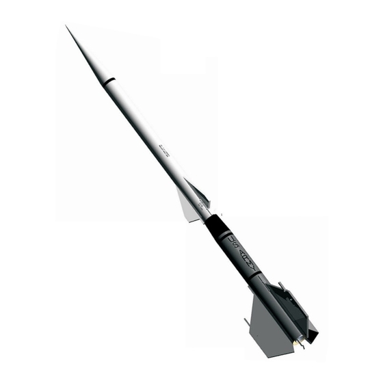
Congratulations on purchasing one of QModeling's
XP Series model rockets - the XP-RAPTOR. The XP
Series is QModeling's original line of top quality
sports class model rockets. The XP-RAPTOR was
designed to leverage existing and extra parts to
produce a sleek and unique original kit. Resembling
a Nike-Ajax the XP-RAPTOR is a based on a BT-60
size main body tube tapering to a BT-55 parachute
compartment. The XP-RAPTOR is over 37 inches
tall and its slender profile and light construction
makes for spectacular high flights.
QModeling's XP-RAPTOR is a 24mm motor design
enabling the use of C, D, E, and F 24mm rocket
motors creating low an incredible high altitude
launches.
It may seem a bit early to speak of
performing a count down, but with QModeling's high
quality laser cut parts and easy step-by-step
instructions your own XP-RAPTOR will be blasting to
new altitudes in no time. QModeling's engine mount,
primary fin design, and professional recovery system
not only helps to ensure correct construction for a
successful first flight, but also increases durability for
long lasting enjoyment
207 Mill Valley Rd, Middleburgh, NY 12122
Phone: (518) 827-3107, Fax: (518) 827-3007
Advertisement

Summary of Contents for QModeling XP Series
- Page 1 Welcome to quality Model Rocketry! XP Series Congratulations on purchasing one of QModeling's XP Series model rockets - the XP-RAPTOR. The XP Series is QModeling's original line of top quality sports class model rockets. The XP-RAPTOR was designed to leverage existing and extra parts to produce a sleek and unique original kit.
- Page 2 Decal and Paint Scheme Renders White Nose Cone Short Stripe Decal White Upper Body Tube /" 8 " CG Loaded Decal (2X) White Secondary Fin Test Conn Decal (3X) Black Transition Long Stripe Decal (2X) US Army Decal (2X) Center Decal /"...
- Page 3 Unpack your XP-RAPTOR and check to make sure all parts are Forward accounted for. If parts are missing contact QModeling by sending an e-mail to tpquinn@qmodeling.com. The (#X) Rocket designator indicates how many of a given part there should be,...
-
Page 4: Assembly Tip
Assembly Tip Read all instructions and locate all parts before beginning assembly. Find or procure all additional items. Organize a suitable work area and layout parts and tools in front of you. Test fit all parts together during each assembly step before applying any glue, especially when using CA. - Page 5 Engine Hook Engine Mount Assembly and Sand edge guide mark smooth Installation (60-75 mins) Engine Hook 1/8" Slot #2 Engine Mount Ring mark Lightly sand the Engine Mount Tube end edges (see figure) smooth using 220 grit sandpaper. Using a /"...
- Page 6 Align the Engine Hook to the Engine Hook Slot Move hook opening and put the hook in place as shown. Test the back and forth movement of the Engine Hook in the slot by moving it back and forth. The hook should move freely when aligned with the Engine Hook guide mark created in step #1.
- Page 7 Remove the Fin Braces and permanently glue all rings to the Engine Mount Tube using Wood glue by running a fillet around each joint as shown. DO NOT GLUE ENGINE HOOK TO ENGINE MOUNT TUBE AND DO NOT RUN A FILLETS ON THE OUTER SIDE Don't run glue fillet OF THE REAR ENGINE RING.
- Page 8 Apply a bead of Wood glue as shown around Apply glue bead as a fillet the Centering Rings and Engine Mount Tube to form a around each joint fillet. AGAIN DO NOT ACCIDENTALLY GLUE ENGINE HOOK OR FILL IN SHOCK CORD HOLE. Don't glue Engine Hook or Shock Cord hole Wrap Shock...
- Page 9 Tack glue Engine Mount in place Keeping the Lower Main Body Tube vertical to allow the glue bead to settle temporarily insert the Primary Fins in place as shown. Adjust the Engine Mount Assembly as needed to ensure the Primary Fins Temporarily install fit and are square to the Lower Main Body Tube.
- Page 10 Using a pencil create the Forward Upper Tube Mark Forward Upper Tube C-Ring location C-Ring marks on the Upper Main Body Tube through the slot in the Fin Template as illustrated. Slide the Fin Template off the Upper Main Body Tube revealing the three line marks and the Forward Upper Tube C-Ring marks.
- Page 11 Slide ring down tube and press in place Locate the third Upper Tube C-Ring and apply a film of Wood Glue to its face. Flip the C-Ring so the glue side is facing forward towards Lower Main Body Align ring glue Tube assembly and slide it down the Upper Main Body face first to tube tube.
- Page 12 Test fit the Transition Cone by sliding it down Test fit the cone by sliding it into place the Upper Main Body Tube. Check the fit around the C- Ring and the tube. Using a pencil mark the rear location Steps of the Transition Cone on the tube.
- Page 13 Take a Primary Fin assembly and apply CA as shown to all surfaces that will contact the Engine Mount Assembly and Main Body Tube. Keeping the Primary Fin assembly square, insert the fin into one of the Main Apply on Body Tube Primary Fin holes and press firmly in place.
- Page 14 Note lug is against bulkhead Locate the supplied Launch Lug tubing and using a hobby knife cut the tubing in half. Determine Apply glue the Primary Fin Launch Lug location by noting relationship to the Engine Hook. The lug should be aligned on the same side as the Engine Hook.
- Page 15 Soak approximately 1“ of the inside surface of the forward end of the Upper Main Body Tube with CA. Use a finger wrapped in a plastic bag to smear CA evenly. Let dry and repeat process. After the CA has dried, sand the inner surface smooth with sandpaper Apply CA and smear to 220 grit or finer.
- Page 16 Finishing Lightly sand off any Check slip fit of Now that your XP-RAPTOR is assembled it is time to plastic flash or bumps Main Nose Cone sand if necessary add the finishing touches. Some modelers view model finishing - sanding, painting, and decaling as torture. Finishing enables you to bring out your personal signature or expression.
- Page 17 Move Spray Can Using hobby masking materials (i.e., Sheet quickly to avoid stock and Tape) mask off the Lower Main Body Tube paint runs assembly roughly mid way down the Transition Cone. Purchase White Enamel Spray Paint from a local Hardware or Hobby store.
- Page 18 Dampen surface Let decals dry thoroughly. Optionally apply an first with water appropriate non-destructive clear coat to the entire rocket to protect decals and paint scheme. Congratulations - on completing your QModeling XP Model RAPTOR!!!
- Page 19 Final Assembly (10-15 mins) Thread Shock Cord through Bumper Locate the Shock Cord Bumper and drill a Shock Cord hole through the center. Pull the Shock Drill Shock Cord hole Cord tautly out of the Main Body tube and thread it through the created hole of the bumper.
- Page 20 National Association of Rocketry Model Rocket Safety Code 1. Materials: I will use only lightweight, non-metal parts for the nose, body, and fins of my rocket. 2. Motors: I will use only certified, commercially-made model rocket motors, and will not tamper with these motors or use them for any purposes except those recommended by the manufacturer.
-
Page 21: Pre-Launch Check List
Pre-Launch Check List Motor Delay Approx Altitude C11-3 200-300 D12-5 500-600 Select an appropriate 24mm rocket engine. E9-6 900-1000 The table shown are engine recommendations that have been tested in the XP-RAPTOR. The actual 24mm engine selected from the availably 24mm engine market is solely the responsibility of the user. -
Page 22: Specifications
Thank you! The staff at QModeling would like to thank you for purchasing our XP-RAPTOR and hopes it will bring you hours of enjoyment. Please visit or web site at www.qmodeling.com and send us feedback on the kit and instructions. Also tell us what unique design aspects you would like to see in the next XP Model. - Page 23 Fin Template C-RING ALIGNMENT SLOTS Main Body Tube SF = Secondary Fins Fin Template Assembly Cut out the above Fin Template Cut out the above Fin Template Fin Template Assembly Roll Fin Template Cut out the Secondary Fin Assembly Template around tube using a pair of scissors.
- Page 24 Pull knot tight apply CA Form a loop using a knot Ensure Retainer Ring is square and tack glue it here GLUE Press glue side against Insert inside wall of tube Shock Cord Knot Apply Glue WOOD Apply GLUE Carpenter or Wood Fold Over Fold Over Completed Mount...
Need help?
Do you have a question about the XP Series and is the answer not in the manual?
Questions and answers